Cloud warping and lost odometry when scanning confined space
Cloud warping and lost odometry when scanning confined space
|
This post was updated on .
Hello,
I am trying to scan a cylindrical confinded space similar to a water well by recording bag files with the Realsense L515 and generating the point cloud with rtabmap_ros. However after a certain time it stops generating local matches and the trayectory starts to bend, causing the point cloud to warp. This space is 24 meters deep and it has a diameter of 1,2 meters. Here are some of the configurations we used to record and process the data, as well as a screenshot of the resulting point cloud: Launching L515: roslaunch realsense2_camera rs_camera.launch align_depth:=true color_width:=640 color_height:=480 color_fps:=30 depth_fps:=30 clip_distance:=3 Selecting camera preset: rosrun dynamic_reconfigure dynparam set /camera/l500_depth_sensor visual_preset 5 Recording .bag files: rosbag record --lz4 -b 1200 --split --size=100 /rtabmap/odom /camera/color/image_raw /camera/aligned_depth_to_color/image_raw /camera/color/camera_info /rosout /rosout_agg /tf /tf_static Processing with rtabmap_ros: roslaunch rtabmap_ros rtabmap.launch \ rtabmap_args:="--delete_db_on_start" \ depth_topic:=/camera/aligned_depth_to_color/image_raw \ rgb_topic:=/camera/color/image_raw \ camera_info_topic:=/camera/color/camera_info \ approx_sync:=false rosbag play *.bag Point cloud after processing: 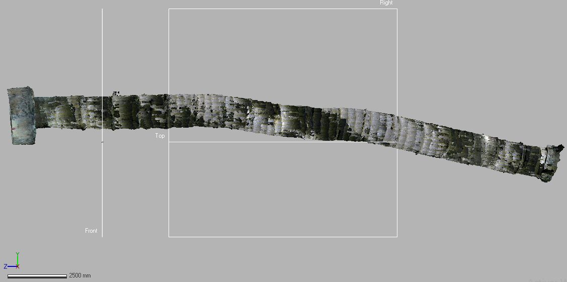 Any help would be really appreciated, Daniel Merizalde. |
|
Administrator
|
Hi Daniel,
RGB-D odometry with L515 cannot be done robustly because the RGB camera is very sensitive to motion blur. If there is a small vibration, the odometry may lose track of features seen in the previous frame, even by assuming you have proper lighting with the camera. To correct orientation, RGBD/NeighborLinkRefining could be enabled with Reg/Strategy=1 for rtabmap node (you would have to provide a downsmapled scan input, see link below). Another idea could be to do icp_odometry instead like in this post: http://official-rtab-map-forum.206.s1.nabble.com/Kinect-For-Azure-L515-ICP-lighting-invariant-mapping-tp7187p7899.html, this is similar to RGBD/NeighborLinkRefining approach above but at higher rate. If there is enough overlap between L515 scans, the tunnel could be quite straight. However, the displacement in the tunnel won't be correctly estimated with icp_odometry alone, icp_odometry may not be able to see that the camera is advancing in the tunnel. To deal with this, rgbd_odometry (which can estimate displacement based on visual features) could be used to provide a guess to icp_odometry, which will align the walls while taking the rgbd_odometry estimated displacement along the tunnel direction. If you can share one rosbag, I could check to make an example of this kind of setup. cheers, Mathieu |
Re: Cloud warping and lost odometry when scanning confined space
|
Hello Mathieu,
First of all, thank you for your help. I tried to process again using Reg/Strategy=1 with these commands: roslaunch rtabmap_ros rtabmap.launch rtabmap_args:="--delete_db_on_start --Reg/Strategy 1 --RGBD/ProximityPathMaxNeighbors 1" depth_topic:=/camera/aligned_depth_to_color/image_raw rgb_topic:=/camera/color/image_raw camera_info_topic:=/camera/color/camera_info approx_sync:=false rosbag play --clock *.bag I obtained similar results as before, as well as some warnings: [ WARN] [1631207313.931432521]: RGBD odometry works only with "Reg/Strategy"=0. Ignoring value 1. [ WARN] (2021-09-09 10:01:51.277) SensorData.cpp:718::uncompressDataConst() Requested laser scan data, but the sensor data (701) doesn't have laser scan. 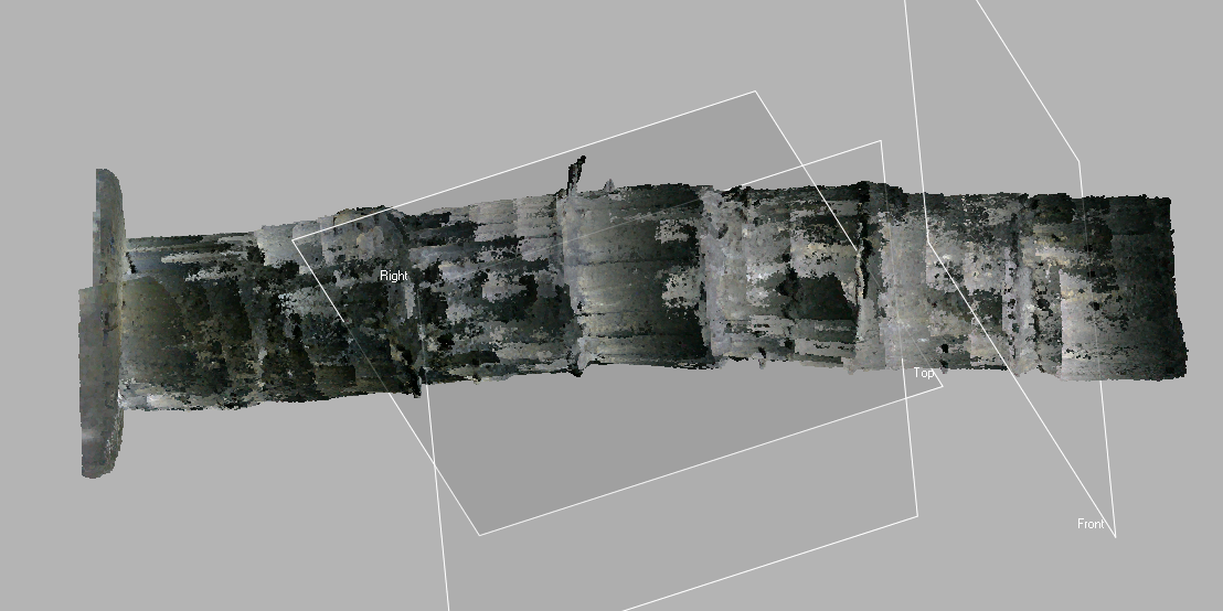 I guess i am not recording enough rostopics to process the data with this approach, do i need to record using the imu_filter_madgwick imu_filter_node and nodelet nodelet standalone rtabmap_ros? I have also tried icp_odometry using the example of the post you linked. It worked really well when generating the clouds in real time, but it was very unstable and odometry got lost when recording the data into rosbag files. However i can give it another try to see how it works and get back to you. I will share the rosbag file example trough the following link: https://drive.google.com/file/d/1F6VwcGBNnijzF80lbg3aTc2HP6N8OZpK/view?usp=sharing As you could see from my rosbag record command i did not record all of the topics given by the L515, so let me know if you need me to record it some other way and the rostopics that would be required for this approach. Thank you! Daniel Merizalde Restrepo. |
|
Administrator
|
Hi Daniel,
I wrongly interpreted the trajectory that was done, it is more a spiral with the camera looking the opposite wall than a straight path towards the bottom (camera looking forward). 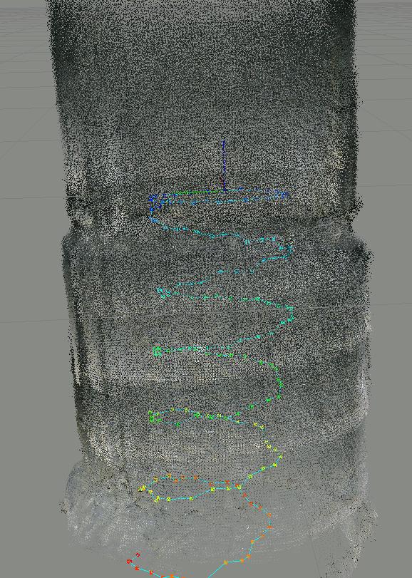 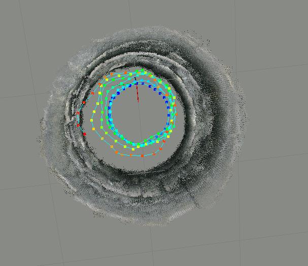 The parameters I used (I increased the local feature map so that after a 360 rotation, odometry can still match features from the last traversal): $ roslaunch rtabmap_ros rtabmap.launch \ args:="-d --OdomF2M/MaxSize 10000" \ depth_topic:=/camera/aligned_depth_to_color/image_raw \ rgb_topic:=/camera/color/image_raw \ camera_info_topic:=/camera/color/camera_info \ approx_sync:=false \ use_sim_time:=true $ rosbag play --clock matlabbe_tunnel_testfile.bag I tried ICP to refine the transformation based on geometry to get the overlapping walls more tighter. However, as it is a tunnel, there are some big drifts doing so (ICP would not see the geometric difference between consecutive scans, so it thinks it didn't move). The point cloud is also relatively noisy, like a stereo point cloud. Is this from a L515? or a D400 camera? Here the noise (I would expect more random noise from a lidar sensor instead of small patches like that, maybe it is because the lidar point cloud has been projected to depth image, losing accuracy, you may try to record the raw lidar point cloud): 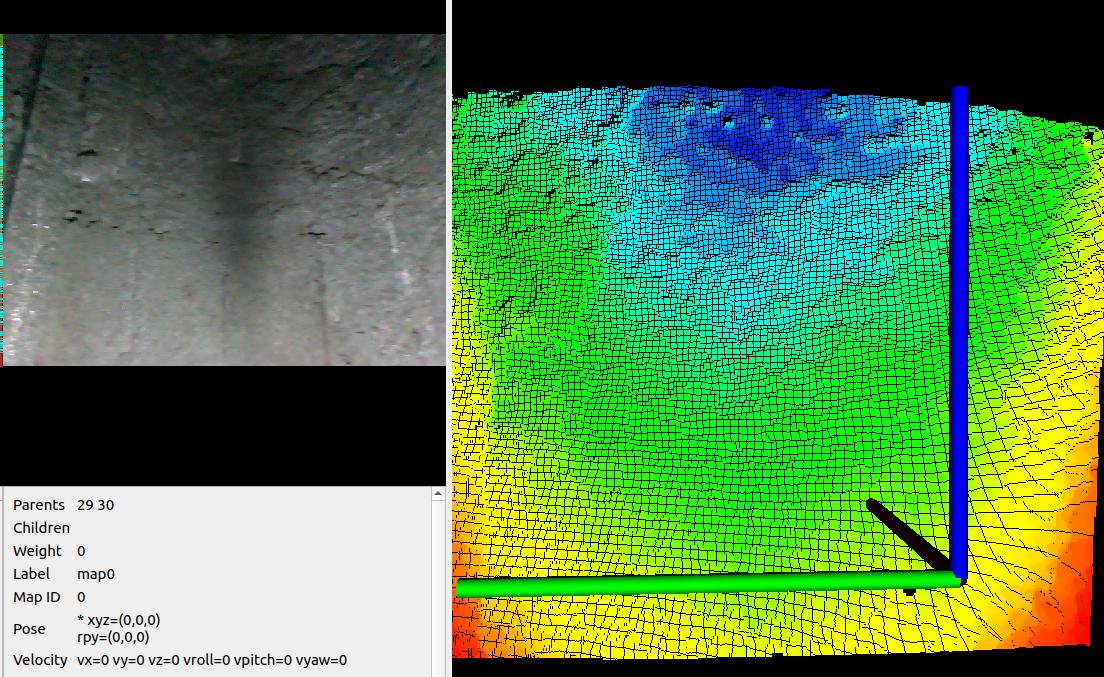 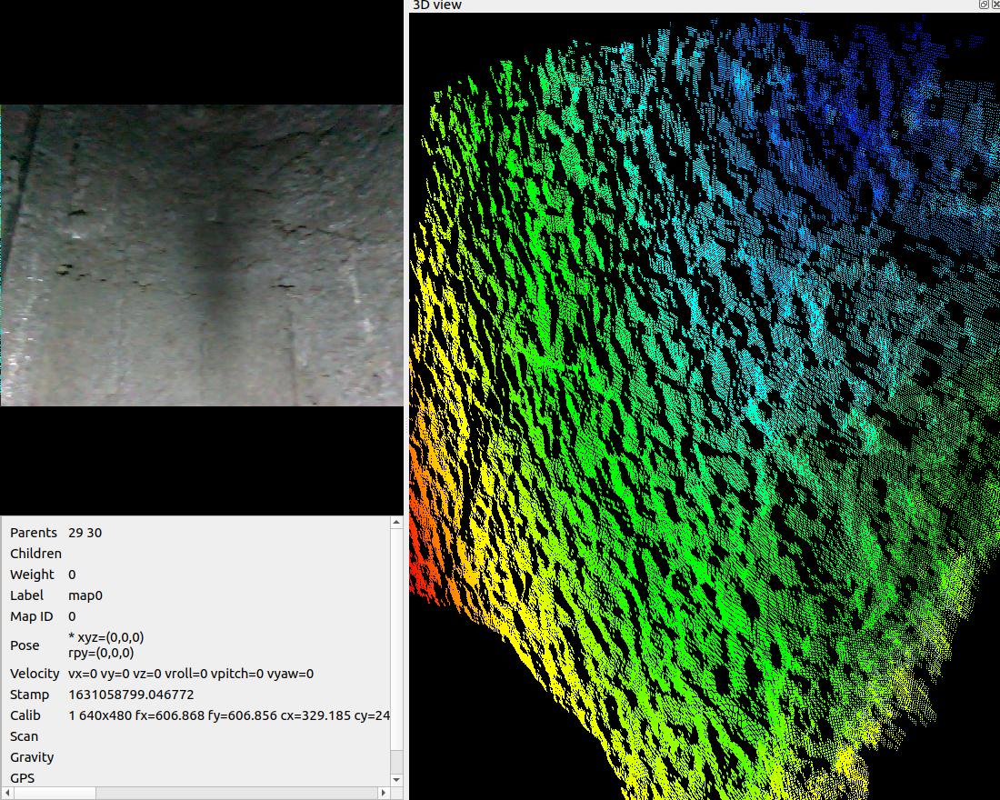 With overlapped consecutive frames, the noise is too high to see where the curve of the tunnel should match together: 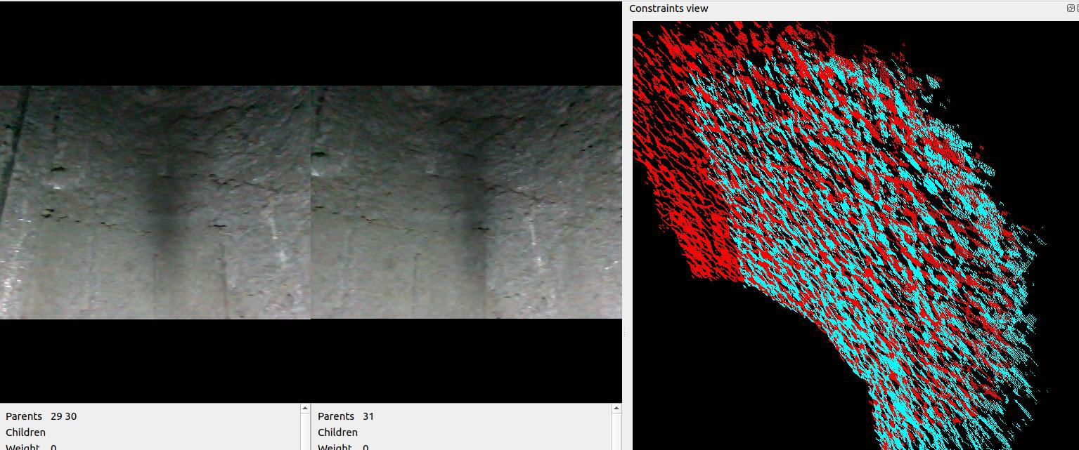 Overall, I didn't see large drift like in your post. If you have a larger bag with the issue, I could take a look. Before sharing rosbags, you can compress them ("rosbag compress my_bag.bag"). Regards, Mathieu |
Re: Cloud warping and lost odometry when scanning confined space
|
Hello Mathiew,
You are correct, the camera is set up following a spiral trayectory as far from the wall as posible in order to deal with the minimum range limitations of the sensor and get as much detail as possible. Do you believe that it would help if it was facing towards the bottom like you described? If so i could run some tests with that configuration. I tried to process the data again using: roslaunch rtabmap_ros rtabmap.launch \ args:="-d --OdomF2M/MaxSize 10000" \ depth_topic:=/camera/aligned_depth_to_color/image_raw \ rgb_topic:=/camera/color/image_raw \ camera_info_topic:=/camera/color/camera_info \ approx_sync:=false \ use_sim_time:=true I got similar results as shown on the following image: 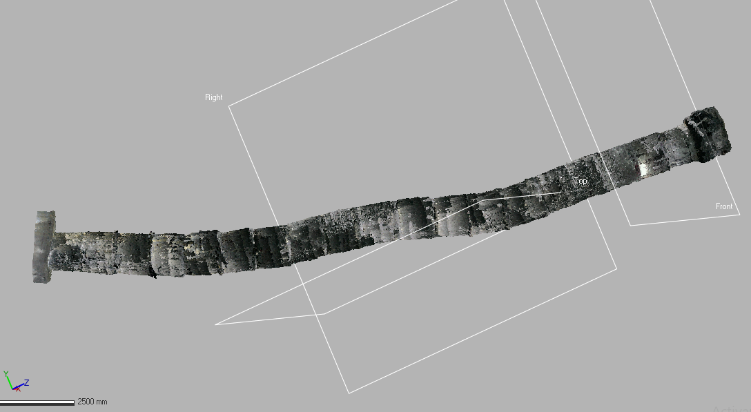 The rosbag file was recorded using a RealSense L515, maybe the lighting conditions inside the tunnel are afecting the sensor and that causes the noise? I will run some tests recording with depth_topic:=/camera/depth/image_rect_raw (which i assume is the raw lidar point cloud) and get back to you with the results. Also, since the L515 will be discontinued, do you have any specific sensor you can recommend for this type of environment? Maybe the rosbag file I sent before was not long enough to start difting, here is a compressed version from a longer dataset where you should see the drifting: https://drive.google.com/file/d/17ibnHstnoYEtmOUJofNQ6xNAZUyZy3E3/view?usp=sharing I also ran some tests on a shorter distance and obtained good results using these parameters: roslaunch realsense2_camera rs_camera.launch align_depth:=true color_width:=640 color_height:=480 color_fps:=30 depth_fps:=30 clip_distance:=3 unite_imu_method:="linear_interpolation" enable_gyro:=true enable_accel:=true rosrun imu_filter_madgwick imu_filter_node \ _use_mag:=false \ _publish_tf:=false \ _world_frame:="enu" \ /imu/data_raw:=/camera/imu \ /imu/data:=/rtabmap/imu rosbag record --lz4 -b 1200 --split --size=100 /rtabmap/odom /camera/color/image_raw /camera/aligned_depth_to_color/image_raw /camera/color/camera_info /rosout /rosout_agg /tf /tf_static /rtabmap/odom \ /camera/color/image_raw \ /camera/aligned_depth_to_color/image_raw \ /camera/color/camera_info \ /rtabmap/odom_info roslaunch rtabmap_ros rtabmap.launch \ rtabmap_args:="--delete_db_on_start --Optimizer/GravitySigma 0.3" \ depth_topic:=/camera/aligned_depth_to_color/image_raw \ rgb_topic:=/camera/color/image_raw \ camera_info_topic:=/camera/color/camera_info \ approx_sync:=false \ wait_imu_to_init:=true \ imu_topic:=/rtabmap/imu However I still need to test it on a longer vertical distance to see if it actually reduces the drift. Thank you very much for your help! Daniel Merizalde Restrepo. |
|
Administrator
|
Hi,
with my command above, I have this: 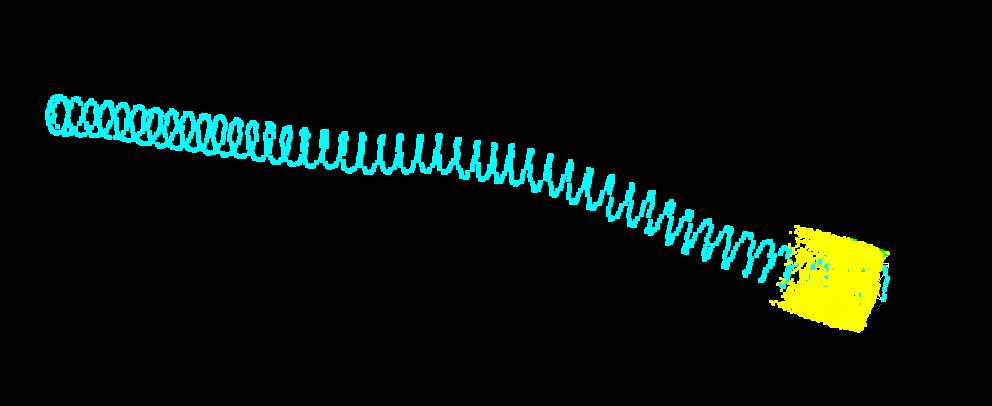 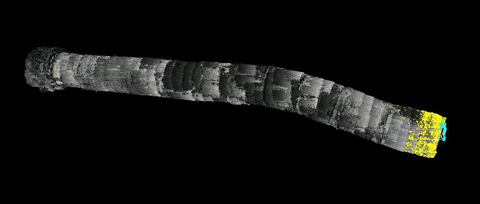 If I do Post-Processing->Detect more loop closures (you can also try with or without SBA): 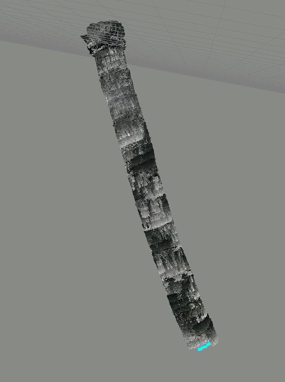 It is better, but the tunnel is still bending. Ideally, we would want more proximity detections between consecutive rings in the spiral to add more constraints, however because of the lighting, it is often difficult to find matches between rings as the top of the image is always darker and the bottom is brighter, making difficult to find correspondences. Here an example: 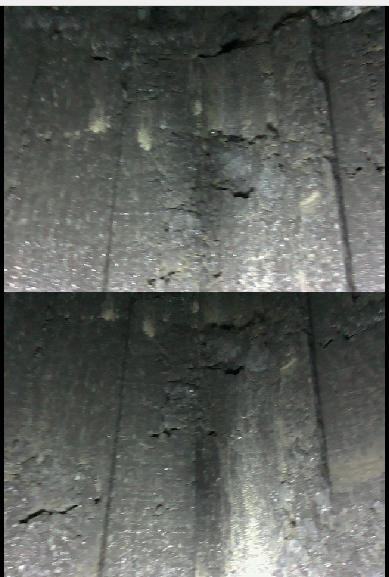 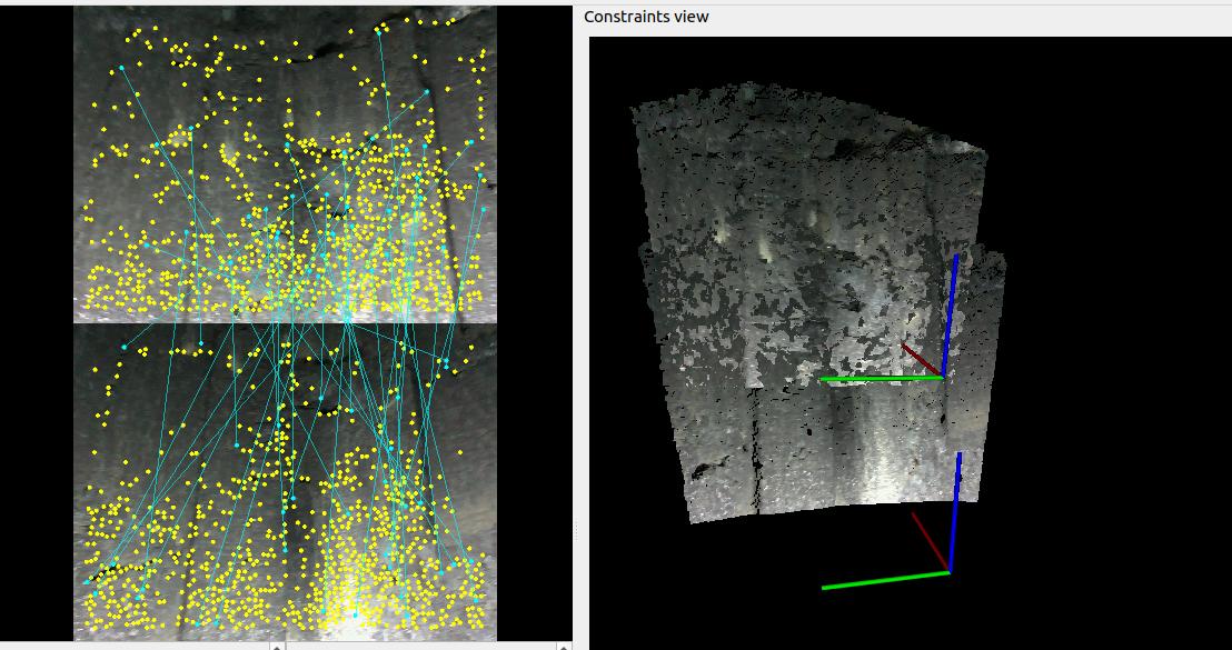 Using SIFT/SURF/SuperPoint as features may help to find more correspondences in such case. Adding another light 40-50 cm over the current one may help to get more uniform lighting. For the cameras, you may try Kinect Azure DK, here is fast comparison (looking at a wall): L515 (note that yellow is the raw LiDAR point cloud, with a slightly larger FOV than the RGB camera, also I checked and between the registered depth and raw depth image, they have exactly the same noise): 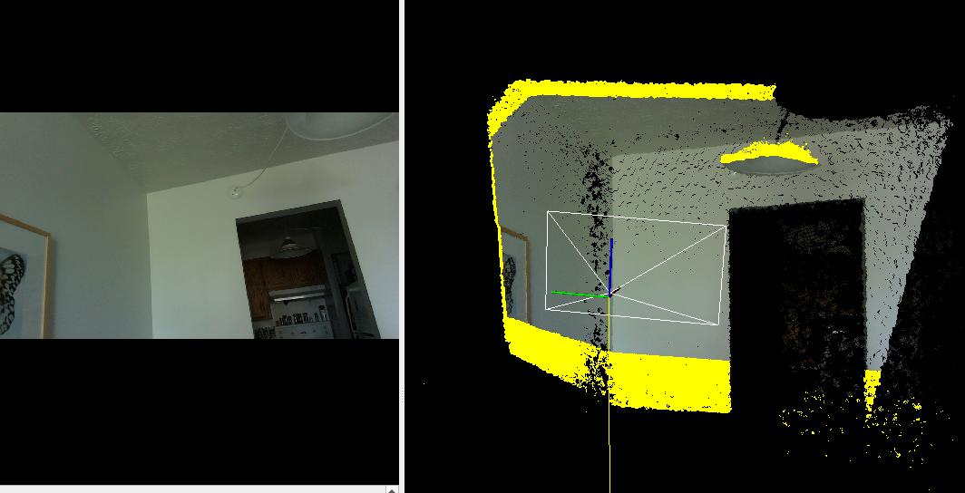 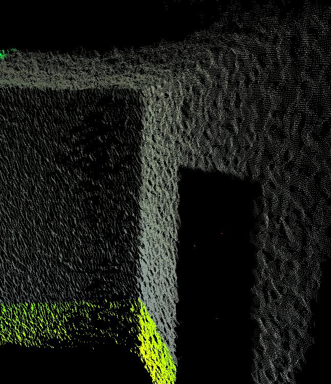 Kinect Azure: 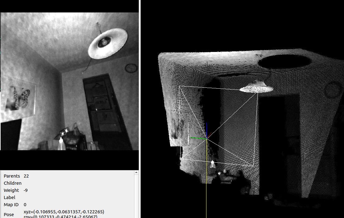 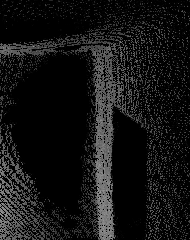 Kinect seems more accurate (a lot smoother) and has also larger FOV. For the question of the trajectory, it depends on the field of view and if you need the texture, but a camera looking down and advancing in a straight line may be possible to get at least the geometry (if it can see the walls on the side in that orientation). cheers, Mathieu |
Re: Cloud warping and lost odometry when scanning confined space
|
Hello Mathiew,
Following your instructions i modified the lighting conditions to make it more uniform and used Post-Processing->Detect more loop closures which generated much better results! I also tried post-processing using SBA but those results were not as good. Also i could not find out how to use SIFT/SURF/SuperPoint so if you could give me a tip or point me to a tutorial i would really appreciate it. Dot cloud with new light setup and post-processing: 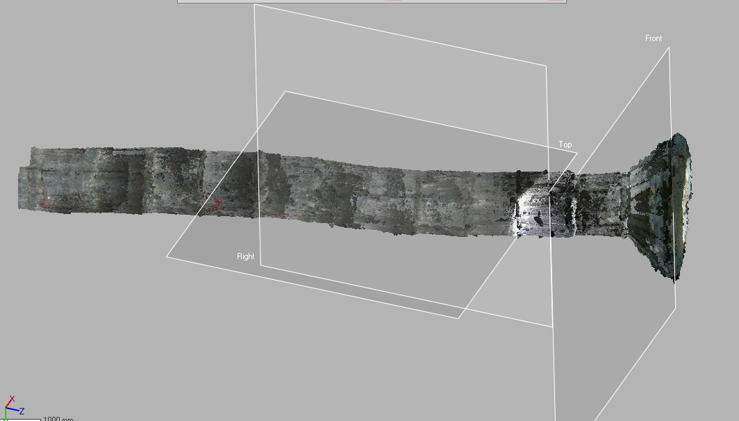 As you can see there is still some bending but it is certainly looking better. Would you suggest that i continue testing with different lights? Do you have any other setup or processing ideas to get a better scan? I could not do any tests with the camera looking down, but will keep it in mind for the future. Thank you for the Kinect recommendation! I will do some more research to see if it could replace the L515. And as always, thank you for your help. Daniel Merizalde Restrepo. |
«
Return to Official RTAB-Map Forum
|
1 view|%1 views
| Free forum by Nabble | Edit this page |

