Hi,
Figure 7 of the
paper summarizes the approach:
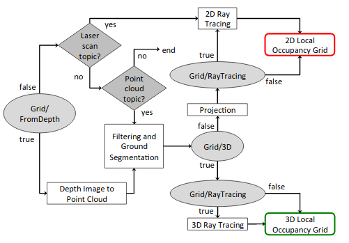
As you are using a stereo camera, the pipeline by default is:
Grid/FromDepth=true
    |->Stereo disparity to point cloud
        |->Filtering and ground segmentation
            |->Grid/3d=false
                |->Grid/RayTracing=False
                    |->2d local occupancy grid.
When doing:
$ rtabmap --params | grep Grid/
you will see more specific parameters (e.g., noise filtering, footprint filtering) that were not shown in the paper. The segmentation approach explained in the paper, based on surface's normals, is selected by the parameter: Grid/NormalsSegmentation=True (default). If the robot is moving on a 2D plane, you may use a more simpler way to segment the ground and obstacles by setting Grid/NormalsSegmentation=False. For example, if you set:
Grid/NormalsSegmentation=False
Grid/MaxGroundHeight=0.03
Grid/MaxObstacleHeight=1
Everything below 3 cm is segmented as ground, and only obstacles between 3 cm and 1 meter are projected as obstacles in the 2d map. Others parameters you may play with are Grid/RangeMax (default 5 meters), which is the maximum range of the local occupancy grid, and Grid/CellSize (default 0.05 m), which is the grid's cell size.
We assume z=0 corresponds to /base_footprint frame of the robot.
Local occupancy grids are assembled depending on the pose graph into the global occupancy grid (Figure 8 of the paper).
cheers,
Mathieu

