Improving a lidar-only setup


|
This post was updated on .
Hi,
We're using a Livox Mid360 as the single sensor with rtabmap. For mapping, we use its IMU for the guess frame for icp_odometry, which in turn provides the odom frame for rtabmap. For localization, we use wheel odometry instead (250Hz and very accurate) and don't use the IMU or icp_odometry anymore. Rtabmap is running at 1Hz, the livox pointcloud output is running at 10Hz (we don't assemble pointclouds). Lidar deskewing is set up and synced with the Livox clock using PTP. This gif is rviz visualizing the deskewed lidar topic in the odometry frame (tf2) (no rtabmap here, just visualizing the input for rtabmap), I see barely any theta accumulation error and neither do I see distortion in the scan, so I assume this is set up correctly.  The area we're working in is a warehouse with ceiling about 30m high and walls 50m away. The majority the livox sees is those and some large pillars, as there's very little tall structures above 2m of the ground and the livox just sees a few parts below 2m above the ground. (and things there often change as well) Now we're wondering how to improve the accuracy of rtabmap. It's a bit tricky to understand what parameters would improve/worsen certain observed problems. If you have input on any of these or general recommendations, that would be greatly appreciated. 1. Arriving on a location from opposing directions doesn't align up well sideways. For the same location the difference is very consistent (within 1cm), but the amount of consistent sideways difference varies from location to location (in ranges up to 15cm) 2. When driving towards a predefined location, the pose rtabmap reports is consistent within 1cm as long as the speed at which we arrived there is the same. If we drive faster towards there, the reported pose tends to lean more towards the right. (up to 10cm further to the right then driving there slowly). This difference is consistent on the same location, but other locations have a different consistent difference. 3. Scan assembling: I assume this is less useful during localization. However, can we have scan assembling during mapping and not during localization? Or does rtabmap require to get a similar scancloud as it got for keypoints? 4. The livox has 360 view, but let's say we mapped in a straight line going e.g. east, it seems that you can't localize in that map if you drive that straight line going west. I assume this is because the pose-graph doesn't related keypoints with different angles but with the same coordinates. Is there some setting to change that? 5. Variances for odometry: If we want rtabmap's 'best absolute pose guess' is it good to put these to e.g. 1e-1, to give higher weight to rtabmap's guess? The aim would be to get as consistent absolute poses regardless of how you got to that location. I would assume putting this to 1e-3 or 1e-4 would make it heavily dependent on odometry not making any mistakes. 6. Voxel size: Can we freely adjust these even if we use a map made at a different voxel size? (similar question for other parameters, are there some that are constrained by what you set them as during mapping?) 7. MaxCorrespondenceDistance: lowering/increasing this, what effect does this have on accuracy and/or rtabmap being able to keep tracking where it is? We're running ros2 jazzy and using the rtabmap binaries. The parameters we're using: rtabmap.yaml Example to hopefully clarify what I mean with the 'sideways' difference. Depending on speed and direction, the vehicle ends up differently (this is due to localization, not control of the robot, I verified) 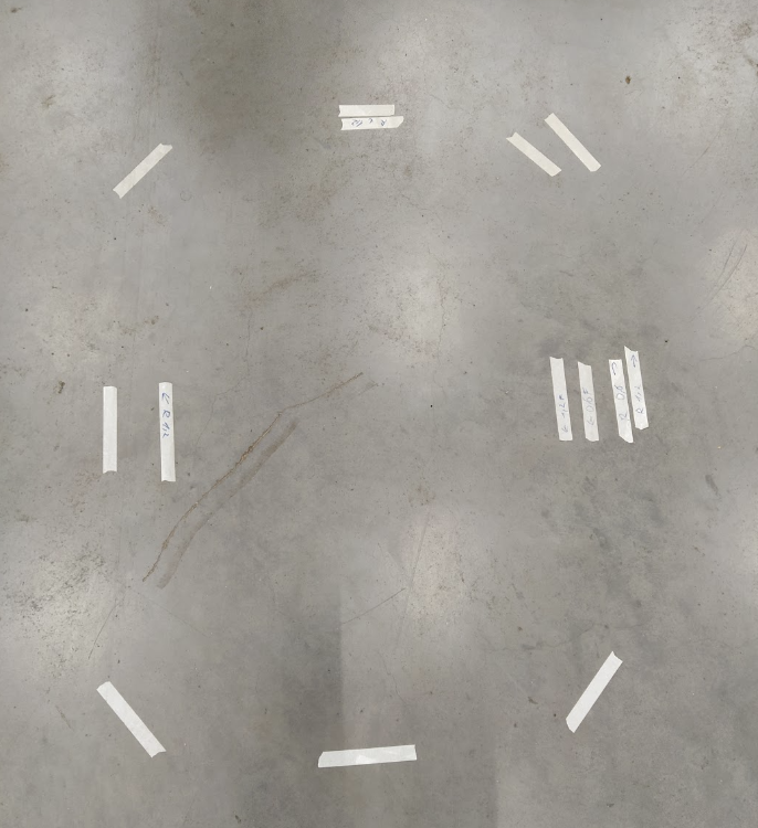
|
|
Administrator
|
Hi,
If you can share a rosbag of the raw lidar data + wheel odom + imu + tf and tf_static, that could be easier for me to recommend which parameters to tune in your case. For your questions: 1. If it varies between localizations, maybe there are some errors in the map, so the robot localizes 10-15 cm the reality. 2. The localization should be independent of speed. Furthermore, I would assume as soon as the robot stops, if it based on speed, it will then know it is off by 10 cm and re-correct itself. If localization is still 10 cm off after stopping and the robot doesn't re-localize correctly, then it would be a map issue (independently of the speed). The speed would influence the deskewing, but as you verified that deskewing works as expected, that could be a map issue. 3. You can assembled only for mapping, only for localization, or both. The only thing is that with assembling the point cloud would be denser, then would influence the parameter "Icp/CorrespondenceRatio", which would need to be set smaller. Using assembled clouds could also give different normals in the point clouds than without assembling, so if Icp/PointToPlane is used, it could affect ICP registration. 4. You should be able to localize in any direction. One type of proximity detection can be affected by RGBD/ProximityAngle parameter, for which you can set to 180 to accept in opposite direction. If the robot is coming back in opposite direction more than 1 meter away, parameter RGBD/ProximityPathFilteringRadius can also be increased. 5. This is mostly relevant for mapping phase. If odometry is not reliable or drifts fast, a large variance should be set, in the other case it is better to keep it as low as possible. The reason is that odometry is used to determinate if a loop closure is good or not. Setting to low while in reality the odometry drifts more could make RTAB-Map rejecting good loop closures. Setting too high while in reality the odometry drift is low could make RTAB-Map accepting bad loop closures. If you do a loop of 100 meters with the robot ending exactly at the same location it started and the drift is 1 meter, then you have a 1% odometry drift. If the robot is moving 50 cm per sec, a variance of 0.05*0.05 could be used. If you use ICP odometry, a covariance will be computed for you based on matching results. 6. Same answer than 3. 7. As a rule of thumb, you can set Icp/MaxCorrespondenceDistance as 10 times the voxel size. That is what I do in my examples. Setting it larger can help to detect loop closures / localize where the robot thinks it is more farther/closer from the reality. In most cases, the ICP results will be pretty much the same. cheers, Mathieu |
|
|
Hi,
I've sent the link to a rosbag to your email. You mentioned that 'I would assume as soon as the robot stops, .... re-correct itself'. I've not really seen that happen. I might be wrong, but it feels that rtabmap with the settings I have is not really updating its estimate when the vehicle is standing still. I'm still playing with the setup myself as well, if I find any more new insights, I'll be sure to share them. |
|
Administrator
|
I think I didn't receive the email.
For the comment "I would assume as soon as the robot stops, .... re-correct itself", I meant just before it stops. By default, RGBD/LinearUpdate and RGBD/AngularUpdate are not zeros, meaning that there is no map update when the robot is completely stopped (under these thresholds). |
|
|
I used the 'send email' on your profile. I've now also sent it straight to your email-address. (topic: "Rosbag for lidar only setup") |
|
Administrator
|
Got your email. I'll take a look later this week. The "Send Email" link on the forum seems indeed not working :(
|
|
Administrator
|
Hi Robin,
I tried the bag using this: ros2 run imu_filter_madgwick imu_filter_madgwick_node --ros-args -p use_mag:=false -p publish_tf:=false -p use_sim_time:=true ros2 launch rtabmap_examples lidar3d.launch.py \ use_sim_time:=true \ frame_id:=runner_2/base_link \ lidar_topic:=/runner_2/localization/livox/points \ voxel_size:=0.2 \ imu_topic:=/imu/data ros2 bag play slow-full-run \ --clock \ --qos-profile-overrides-path durability_override.yaml \ --remap /runner_2/localization/livox/imu:=/imu/data_raw Note that my computer is running ROS2 Humble, so I needed to run this to convert the bag to be compatible. Then run the bag with a durability_override.yaml to make /tf_static transient QOS. # durability_override.yaml /tf_static: durability: transient_local history: keep_all Because the lidar looks like on a pole on the robot, the oscillations are noticeable, so I think the best results are achieved by using the IMU for deskewing. With this setup, the results looks pretty good. Comparing the first and last clouds, they overlap nicely. 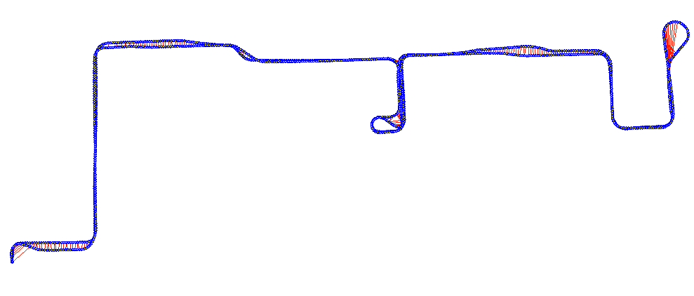 Even without loop closure optimization, the trajectory is close to the optimized one above (less than 10 cm of error between the first and last pose): 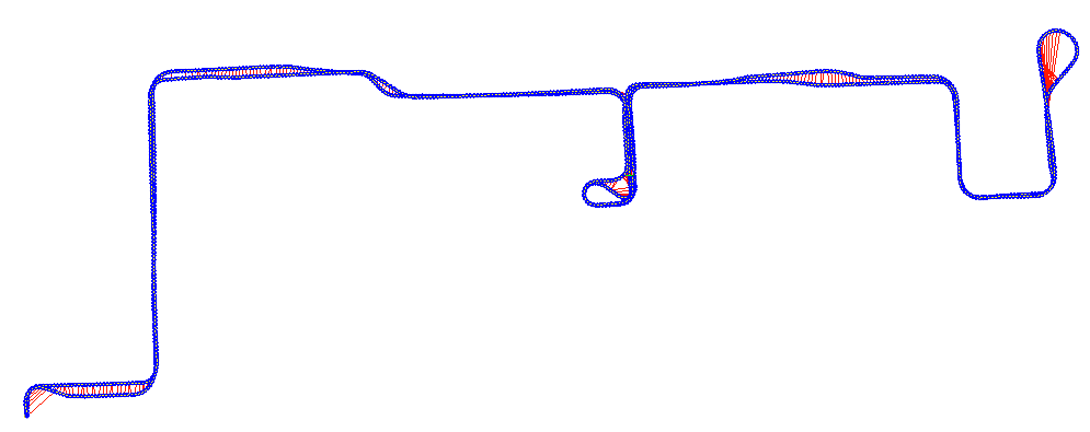 There are no IR or RGB images from the depth cameras, so if you want an example with the cameras integrated (useful for re-localization), I could try another bag. Otherwise, if you try my example above with same bags, if you have still issues, it will be easier for me to compare with what I get. cheers, Mathieu |
|
|
Hi Mathieu,
Thanks for the time and effort! The original problem I had with sideways deviations depending on speed seems to be resolved. Not sure yet exactly why though. I've adjusted some settings, but I've also very accurately calibrated the scaling of the wheels for wheel odometry and the 6D pose of the livox to the baseframe. The previous values for those were already pretty accurate to like 5mm or 0.5 degrees. I'll be testing reverting some of those changes and seeing when I can reproduce the problem. My current parameters: params.yaml Most, if not all, of my parameters in my original post were based on your lidar3d.launch.py. So if you're saying that result looks good, maybe my problem was more related to the localization. The robot is 2m tall, with the livox on top, so yes, it will have noticeable oscillations. About using the IMU for deskewing though, I'm wondering about the effect of velocity (and acceleration). Using imu_to_tf + lidar_deskewing will only account for angle changes, right? So constant robot speed is not accounted for and non-constant swaying of the sensor neither. Only the impact on roll/pitch oscillations would be captured? Would using something like robot_localization to combine wheel odometry + imu be a good approach for the deskewing? Some other questions: - Every time I do a mapping, I afterwards have to do rtabmap-recovery, as the database consistently is corrupted. I don't know if there's something I'm doing wrong here. When done mapping, I pause in rtabmap_viz and then I ctrl-C the launch. ("Database is indeed corrupted, found one or more neighbor links missing.") - What metrics do you generally look at and where (rtabmap-databaseViewer?). Specifically how you would compare the quality of the mapping or localization when changing parameters when there's no ground truth available. Currently I try to use wheel odometry as the ground truth, but that's not that great of course. Next week I probably will have time to make new ros bags that would be including the IR and RGB images of the two cameras and also calibrated wheel odometry and calibrated TF transforms for livox and cameras. |
|
Administrator
|
Hi Robin,
Yes, Yes, and maybe. If there is some linear motion between two lidar captures, you may try to estimate it with an EKF filter, but beware to not add more error. In my experience, the angular accuracy is more important than linear accuracy for deskewing (at least for indoor "slow" robots, estimating linear velocity would be required with fast robots like drones or robot cars). For example, if your robot is moving at constant 0.3 m/s and scans are taken at 10 Hz, you could have at most 3 cm error between the first lidar capture and the last one, which is often close to lidar noise. I think the robot was moving even slower, so the error could be even less that, maybe below 1cm, which is probably less than the lidar noise. That is strange, maybe rtabmap doesn't have time to correctly close the database when it is killed. If you show logs in terminal, make sure you see those logs when you are shutting down rtabmap node: [rtabmap-2] rtabmap: Saving database/long-term memory... (located at /home/mathieu/.ros/rtabmap.db) [rtabmap-2] rtabmap: Saving database/long-term memory...done! (located at /home/mathieu/.ros/rtabmap.db, 42 MB) I use rtabmap-databaseViewer a lot to debug many things. The Statistics panel is useful to analyze processing time. To estimate how good a trajectory is without a ground truth, I generally make a trajectory that ends where it started (putting a tape on the floor and make sure to move back the robot exactly at the same starting position), then in rtabmap-databaseViewer, you can open Graph View, then there is a slider for the number of iterations, sliding all way to left will show the trajectory without loop closures (pure odometry), you can compare how far the first and last poses are from each other. The Constraints View is also useful to compare scans between some nodes to see if they are correctly aligned or not. cheers, Mathieu |
|
|
This is what I get when I ctrl-C my launch (I just stopped it after a minute or so of mapping with a rosbag). Could be related to my setup though, so not sure if this is a bug. I'm running in a devcontainer (using jazzy and zenoh rmw).
[rtabmap-7] [DEBUG] [2025-05-12 09:53:11.710] [rcl]: Subscription take succeeded: true
[rtabmap-7] [DEBUG] [2025-05-12 09:53:11.713] [rcl]: Subscription taking message
[rtabmap-7] [DEBUG] [2025-05-12 09:53:11.713] [rcl]: Subscription take succeeded: true
[rtabmap-7] [DEBUG] [2025-05-12 09:53:11.714] [rcl]: Subscription taking message
[rtabmap-7] [DEBUG] [2025-05-12 09:53:11.714] [rcl]: Subscription take succeeded: true
^C[WARNING] [launch]: user interrupted with ctrl-c (SIGINT)
[rtabmap-7] [INFO] [2025-05-12 09:53:11.715] [rclcpp]: signal_handler(signum=2)
[rtabmap-7] [DEBUG] [2025-05-12 09:53:11.715] [rclcpp]: signal_handler(): notifying deferred signal handler
[rtabmap-7] [DEBUG] [2025-05-12 09:53:11.715] [rclcpp]: deferred_signal_handler(): woken up due to SIGINT/SIGTERM or uninstall
[rtabmap-7] [DEBUG] [2025-05-12 09:53:11.715] [rclcpp]: deferred_signal_handler(): shutting down
[rtabmap-7] [DEBUG] [2025-05-12 09:53:11.715] [rclcpp]: deferred_signal_handler(): shutting down rclcpp::Context @ 0x5f53cdeec010, because it had shutdown_on_signal == true
[rtabmap-7] [DEBUG] [2025-05-12 09:53:11.715] [rcl]: Shutting down ROS client library, for context at address: 0x5f53cdeea700
[rtabmap-7] [DEBUG] [2025-05-12 09:53:11.716] [rcl]: Finalizing publisher
[rtabmap-7] terminate called after throwing an instance of 'std::runtime_error'
[rtabmap-7]   what():  context cannot be slept with because it's invalid
(As for speed of the robot, that rosbag was indeed about 0.3m/s, as it's intended to make a map. In reality the robot on average drives 1.2m/s and at max 2m/s) And thanks for the tips with databaseViewer, that's really helpful! |
|
Administrator
|
I checked on my computer, and the closing logs should look like this:
ros2 run rtabmap_slam rtabmap -d --ros-args --log-level debug

<ctrl-c>

^C[INFO] [1747519798.830341876] [rclcpp]: signal_handler(signum=2)
[DEBUG] [1747519798.830414897] [rclcpp]: signal_handler(): notifying deferred signal handler
[DEBUG] [1747519798.830538703] [rclcpp]: deferred_signal_handler(): woken up due to SIGINT/SIGTERM or uninstall
[DEBUG] [1747519798.830590741] [rclcpp]: deferred_signal_handler(): shutting down
[DEBUG] [1747519798.830734759] [rclcpp]: deferred_signal_handler(): shutting down rclcpp::Context @ 0x639e109b76f0, because it had shutdown_on_signal == true
[DEBUG] [1747519798.830764990] [rcl]: Shutting down ROS client library, for context at address: 0x639e109bafe0
[DEBUG] [1747519798.830840216] [rcl]: Finalizing publisher
[DEBUG] [1747519798.832016428] [rcl]: Publisher finalized
[DEBUG] [1747519798.832059038] [rcl]: Finalizing publisher
[DEBUG] [1747519798.832335566] [rcl]: Publisher finalized
[DEBUG] [1747519798.832475203] [rclcpp]: deferred_signal_handler(): waiting for SIGINT/SIGTERM or uninstall
[DEBUG] [1747519798.832495209] [rclcpp]: SignalHandler::uninstall(): notifying deferred signal handler
[DEBUG] [1747519798.832540555] [rclcpp]: deferred_signal_handler(): woken up due to SIGINT/SIGTERM or uninstall
[DEBUG] [1747519798.832551930] [rclcpp]: deferred_signal_handler(): signal handling uninstalled
[DEBUG] [1747519798.832680552] [rclcpp]: signal handler uninstalled
[INFO] [1747519798.881312456] [rtabmap]: Parameters are not saved (No configuration file provided...)
rtabmap: Saving database/long-term memory... (located at /home/mathieu/.ros/rtabmap.db)
rtabmap: Saving database/long-term memory...done! (located at /home/mathieu/.ros/rtabmap.db, 0 MB)
Based on your log, maybe that error is happening if an external node is subscribed to one specific publisher (which one? not sure how to know that) from rtabmap node: [rtabmap-7] [DEBUG] [2025-05-12 09:53:11.716] [rcl]: Finalizing publisher [rtabmap-7] terminate called after throwing an instance of 'std::runtime_error' [rtabmap-7] what(): context cannot be slept with because it's invalidThe only similar post I've found: https://github.com/ros2/ros2/issues/1659, which seems also related to a publisher. Can you try to run only the rtabmap node like I did to see if the error still happen on your side? |
|
|
I ran it the exact same way and I also switched my setup to default rmw instead of zenoh and now ran it outside of docker. So afaik the only difference with your setup is I'm running jazzy on ubuntu noble.
   PLATFORM INFORMATION
system           : Linux
platform info    : Linux-6.9.3-76060903-generic-x86_64-with-glibc2.39
release          : 6.9.3-76060903-generic
processor        : x86_64

   QOS COMPATIBILITY LIST
compatibility status    : No publisher/subscriber pairs found

   RMW MIDDLEWARE
middleware name    : rmw_fastrtps_cpp

   ROS 2 INFORMATION
distribution name      : jazzy
distribution type      : ros2
distribution status    : active
release platforms      : {'debian': ['bookworm'], 'rhel': ['9'], 'ubuntu': ['noble']}
The log ros2 run rtabmap_slam rtabmap -d --ros-args --log-level debug ... ^C[INFO] [1748355542.137371437] [rclcpp]: signal_handler(signum=2) [DEBUG] [1748355542.137435127] [rclcpp]: signal_handler(): notifying deferred signal handler [DEBUG] [1748355542.137513694] [rclcpp]: deferred_signal_handler(): woken up due to SIGINT/SIGTERM or uninstall [DEBUG] [1748355542.137551917] [rclcpp]: deferred_signal_handler(): shutting down [DEBUG] [1748355542.137686506] [rclcpp]: deferred_signal_handler(): shutting down rclcpp::Context @ 0x62d2ae08fa20, because it had shutdown_on_signal == true [DEBUG] [1748355542.137718033] [rcl]: Shutting down ROS client library, for context at address: 0x62d2ae017820 [DEBUG] [1748355542.137788282] [rcl]: Finalizing publisher terminate called after throwing an instance of 'std::runtime_error' what(): context cannot be slept with because it's invalid [ros2run]: Aborted On another note, as mentioned earlier, I made new ros bags including the camera-feeds. I've sent them to your email, so feel free to have a look if you're interested to. I wasn't sure whether I should have the emitter enabled or not, but decided in the end to enable it and capture rgb, aligned_depth_to_color, point-cloud and both infra topics. |
|
Administrator
|
The exception issue has been fixed in this commit.
I'll check later for your rosbags. Thanks for sharing. |
|
Administrator
|
I looked at the rosbags with camera, and below is a launch file integrating both cameras with the 3D lidar. Note that this commit is required to make it work.
# example.launch.py: Example lidar3d with 2 realsense cameras

import os

from ament_index_python.packages import get_package_share_directory

from launch import LaunchDescription, LaunchContext
from launch.actions import DeclareLaunchArgument, OpaqueFunction
from launch.substitutions import LaunchConfiguration
from launch_ros.actions import Node, SetParameter
from launch.actions import IncludeLaunchDescription
from launch.launch_description_sources import PythonLaunchDescriptionSource

import tempfile

def launch_setup(context: LaunchContext, *args, **kwargs):

  lidar3d_launch_file = 'lidar3d.launch.py'
  return [
    SetParameter(name='use_sim_time', value=LaunchConfiguration('use_sim_time')),

    # Sync rgb/depth/camera_info together for the first camera
    Node(
        package='rtabmap_sync', executable='rgbd_sync', name='rgbd_sync1', output='screen',
        parameters=[{'approx_sync': False}],
        remappings=[('rgb/image', '/runner_2/obstacle/left/camera/color/image_raw'),
                    ('rgb/camera_info', '/runner_2/obstacle/left/camera/color/camera_info'),
                    ('depth/image', '/runner_2/obstacle/left/camera/aligned_depth_to_color/image_raw'),
                    ('rgbd_image', '/runner_2/obstacle/left/camera/rgbd_image')]),

    # Sync rgb/depth/camera_info together for the second camera
    Node(
        package='rtabmap_sync', executable='rgbd_sync', name='rgbd_sync2', output='screen',
        parameters=[{'approx_sync': False}],
        remappings=[('rgb/image', '/runner_2/obstacle/right/camera/color/image_raw'),
                    ('rgb/camera_info', '/runner_2/obstacle/right/camera/color/camera_info'),
                    ('depth/image', '/runner_2/obstacle/right/camera/aligned_depth_to_color/image_raw'),
                    ('rgbd_image', '/runner_2/obstacle/right/camera/rgbd_image')]),

    # Sync two cameras together
    Node(
        package='rtabmap_sync', executable='rgbdx_sync', output='screen',
        parameters=[{'approx_sync': True, 'rgbd_cameras': 2}],
        remappings=[('rgbd_image0', '/runner_2/obstacle/left/camera/rgbd_image'),
                    ('rgbd_image1', '/runner_2/obstacle/right/camera/rgbd_image'),
                    ('rgbd_images', '/runner_2/obstacle/rgbd_images')]),

    # Filtering imu
    Node(
        package='imu_filter_madgwick', executable='imu_filter_madgwick_node', output='screen',
        parameters=[{'use_mag': False, 'publish_tf': False}],
        remappings=[('imu/data_raw', '/runner_2/localization/livox/imu/raw'),
                    ('imu/data', '/runner_2/localization/livox/imu')]),

    # Launch rtabmap
    IncludeLaunchDescription(
        PythonLaunchDescriptionSource(os.path.join(
            get_package_share_directory('rtabmap_examples'), 'launch/lidar3d.launch.py')),
        launch_arguments={'use_sim_time': LaunchConfiguration('use_sim_time'),
                          'voxel_size': '0.2',
                          'frame_id': 'runner_2/base_link',
                          'lidar_topic': '/runner_2/localization/livox/points/raw',
                          'imu_topic': '/runner_2/localization/livox/imu',
                          'rgbd_images_topic': '/runner_2/obstacle/rgbd_images'}.items()),
  ]

def generate_launch_description():
  return LaunchDescription([
    # Launch arguments
    DeclareLaunchArgument(
      'use_sim_time', default_value='false',
      description='Use simulated time'),

    OpaqueFunction(function=launch_setup),
  ])
Usage: ros2 launch example.launch.py use_sim_time:=true ros2 bag play fast-848 --clock --qos-profile-overrides-path durability_override.yaml --remap /tf:=/tf_ignoredSee previous posts for "durability_override.yaml" (tested on humble). I noticed that the camera data is actual not that useful because the depth is poorly estimated. Looking at the IR images, we can see a lot of glare / reflections in the cameras, possibly the cause why depth estimation is very poor. I am not sure what is causing the glare (is there another glass in front of the camera? are the lens dirty?). This example use RGB-D data from realsense cameras, it could be also possible to use left IR + Depth for better accuracy, but IR emitter would need to be disabled. cheers, Mathieu |
|
|
Hi,
Sorry for the late response. I finally had time to dive into this again. - The fix for the clean shutdown indeed works, thx! - Our cameras are indeed behind some glass, so the emitter is creating reflections. So we'll just stick with no emitter and infra+depth. Btw, in case this is helpful info for you, for getting to localize far from the mapped paths, I adjusted these parameters compared to the defaults in the lidar3d.launch.py example: - RGBD/LocalRadius: 30.0 - RGBD/ProximityPathMaxNeighbors: 2 - Icp/CorrespondenceRatio: 0.1 Because the livox 360 has a large range and fov, the localization remains pretty accurate even when far from any mapped location. Currently we're trying to get the most out of rtabmap in terms of repeatability. Do you have any suggestions which parameters to focus on? I know this is not a trivial question and depends on quite a few factors. When localizing in pretty much the exact same scenario (same start/end location and same speed profile), we get roughly +-5mm deviation at most. When we change the start location and/or the speed profile though, this becomes something like +-15mm deviation. Our ideal goal would be +-3mm in all cases where the last 2 meters of movement can be at slower speeds. Some notes about the use case: - the above tests are movements to/from for a distance of about 5 meters, with varying turns and speeds and always containing a quarter pivot + 0.5m linear movement near the end. - rotation speeds of the vehicle go up to at most 1.2rad/s, linear movement speeds go up to 2m/s - 90% of the pointcloud features are ceiling/walls that are 20m+ away As said in my previous posts here, we've already ensured very accurate odometry calibration, lidar deskewing, static tf for lidar and timestamp sync of the sensor. Aside from parameter trial/error and tuning, we were thinking of maybe incorporating markers for critical locations as well, but I'm not sure if that's going to give more trouble than benefit. If the marker is obscured, I would assume that affects repeatability for example. Any guidance on which parameters to focus on or anything else is greatly appreciated! |
|
Administrator
|
I checked on their website and the Mid360 has these specifications:
Range Precision³ (1σ)
≤ 2 cm ⁴ (@ 10m)
≤ 3 cm ⁵ (@ 0.2m)
Angular Precision(1σ )
< 0.15º
so a deviation of +-15 mm seems inside their specifications (particularly when 90% of the points are taken 20 meters away). In general, I would expect localization accuracy in the range of the sensor noise. To improve accuracy, on rtabmap side I cannot really see what you can do more. From what I understand, you want +- 3mm on global localization and rtabmap node gives around +- 15 mm. I think to get under 5 mm global localization accuracy, you could add more physical structures (with complex geometry) around critical poses so that the lidar gets its most precision (with points closer to the robot). As you mentioned, another approach is to use markers to refine the last mm of localization. For one AMR I worked on, they were using industrial apriltag/aruco-like detection sensor under the vehicle. The tags were on the floor and the robot moved over them, with a sensor under the robot looking at the ground. Rtabmap can record and re-localize on tags (see supported landmark/tag topic inputs), so it could localize the robot close enough to the tags, then another controller was locally "visual servoing" as soon as the tag was in field of view of the sensor for very accurate position. In your case, it depends if you need high accuracy when moving between stations and/or just at the working stations. For high accuracy all the time, then the tags won't really help (because putting tags everywhere would be similar to use an AGV instead, by taping a line or add a magnetic wire on the floor). cheers, Mathieu |
«
Return to Official RTAB-Map Forum
|
1 view|%1 views
| Free forum by Nabble | Edit this page |