RTAB-Map and Unity integration


|
Hi,
I'm trying to use a RGB-D camera connected to a remote robot to construct a 3d map of a small environment and render this in real time using Unity (that is, update the map while it is being built). I've been playing with rtab-map for a couple of days and it seems to give me very good quality maps. The Unity part, on the other hand, has been trickier... I have a few general related questions:
1) From this issue, I understood this integration is not officially supported, but has anyone successfully done it before? If so, could you give me some pointers?
2) From Unity, I'm already able to read a point cloud message, so this would be the preferred input method in my case. I see that I can get a live update of the map from /rtabmap/cloud_map, but is this the same information that I get from /rtabmap/mapData? Or is it before optimization?
3) Am I missing some obvious bottleneck that would prevent this application from working?
Thank you in advance for any help.
|
|
Administrator
|
Hi,
1) I don't think so 2) Yes, cloud_map has the same data than mapData. It will be optimized on loop closures and it is voxelized at 5 cm by default, see Grid/CellSize parameter. 3) It is more efficient to use mapData and reconstruct the point cloud on client side. The whole point cloud doesn't need to be streamed at each update, only latest data added to map. See rviz MapCloud plugin on how to use that topic. In processMapData(), we create the cloud of the latest node added to graph. In update(), we move all clouds accordingly to their optimized pose (we just update the pose of the cloud's root transform). cheers, Mathieu |
Re: RTAB-Map and Unity integration
|
|
This post was updated on .
Hi Mathieu,
Thanks for the reply. I'll look into what you suggested on the third option and report back here next week if I have success. Cheers, Vinicius |
Re: RTAB-Map and Unity integration
|
|
Hi again,
Sorry for the delay in replying, but this has been harder than I initially expected. I've decided to start with a pre-built map loaded in Unity and just update the position according to the robot localization, because this is easier to implement and also to explore a best case scenario of what could be achieved in terms of visualization. So, I'm trying to get the 3d map using rtabmap. However, I'm facing this problem where the clouds don't get correctly aligned, leading to double walls and distorted objects, as seen in the figures below. 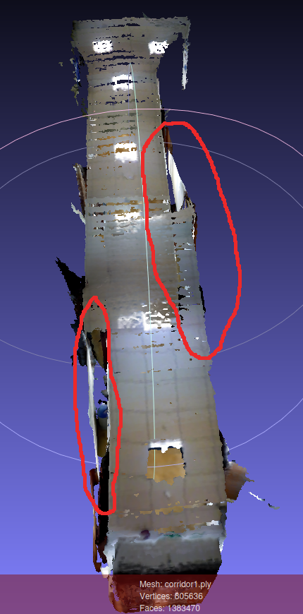 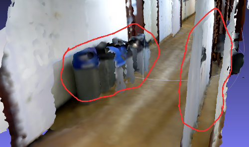 This happens even after loop closure is detected. I've tried many different things and no success, so I was hoping that maybe you could have some insight to help me. Follows a description of my setup and observations: I'm using Ubuntu 16.04 and ROS Kinetic. The robot I'm using has laser scanners with 360 degrees laser coverage, but no wheel encoders, so I'm using a slightly modified version of this to do the mapping. I'm trying to map a corridor with an Asus Xtion camera, by going one way, back and then another half rotation for loop closure detection. I noticed that the points relative to the right wall are always a bit shifted from the laser readings, which messes up the map. When loop closure is detected, the grid map from hector_mapping gets corrected, but not the point cloud map. When I run hector_mapping alone, I don't see any distortion between the laser readings and the map. I think that setting "RGBD/NeighborLinkRefining" parameter to true helped a little, but not much. Also, during runtime, rtabmap keeps throwing this error below but continues to run normally. From what I read on another post here on the forum I understood that it is safe to ignore this, right? [ERROR] (2018-08-31 17:19:51.847) Memory.cpp:815::addSignatureToStm() Failed to invert the covariance matrix! Covariance matrix should be invertible! Covariance: [12.03116893768311, -2.387195825576782, 0, 0, 0, 139.1024169921875; -2.387195825576782, 32.27930450439453, 0, 0, 0, 249.5898590087891; 0, 0, 0, 0, 0, 0; 0, 0, 0, 0, 0, 0; 0, 0, 0, 0, 0, 0; 139.1024169921875, 249.5898590087891, 0, 0, 0, 32290.607421875] To reproduce the problem, I've uploaded here a compressed bag file of a sample run, my roslaunch file, the unmodified rtabmap database that was saved when the run finished, and two .ply mesh files generated, with the above parameter set or unset. Like I said, I've run out of ideas on how to fix this, so really appreciate any help. And sorry for the long post! Cheers, Vinicius |
|
Administrator
|
Hi,
The 2D map created by rtabmap is fine:  The scans look correctly registered, but not the point clouds: 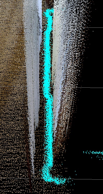 It means that the transform (TF) between the base frame of the robot and the camera frame is not accurate (well, it could be also the transform between base frame and laser frame). We can see better looking with rtabmap-databaseViewer at data of a node: 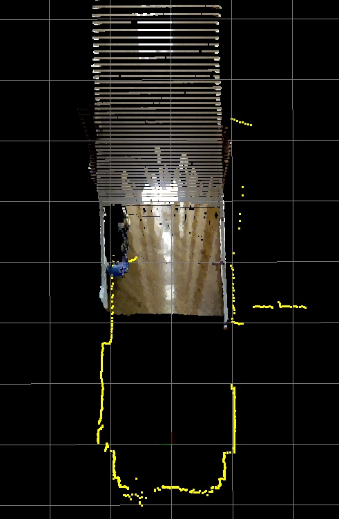 There is a small rotation (in yaw) and a small offset between the lidar and the camera. To debug this with RVIZ, show the live point cloud of the camera in base frame of the robot while showing the laser scan, the laser scan should match the point cloud if TF between robot base and your sensors is correctly set. cheers, Mathieu |
Re: RTAB-Map and Unity integration
|
|
Hi Mathieu,
Thanks for the help, that was indeed the problem. I got lost on tuning the parameters and missed the most clear sign. Cheers, Vinicius |
Re: RTAB-Map and Unity integration
|
|
Hi Mathieu,
Sorry for bothering so much, but again I'm having problems building the map. It's basically the same setup as before, I just added some obstacles on the way. After mapping, however, the obstacles get all distorted, as in the pictures below. I've tried changing the static transforms between base and camera links in many ways, but the distortion always persists in one way or another. 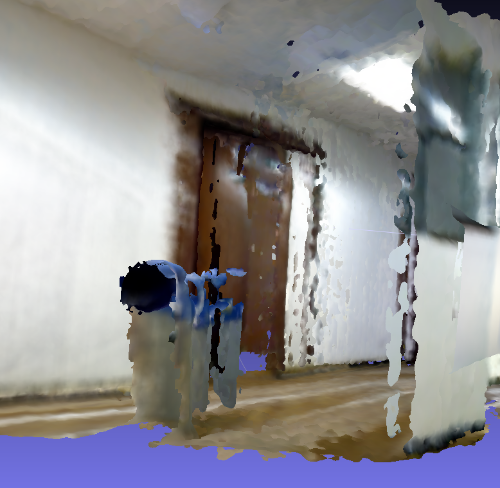 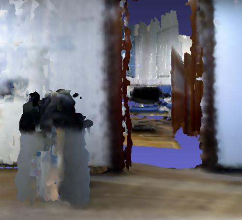 I've added some bag files of my best runs here (images compressed and throttled at 10hz). Is there some parameter that I'm setting wrong? Do you have some tip on how to improve the quality of the map? Cheers, Vinicius |
|
Administrator
|
As TF is not recorded, we cannot test the bags, arta_description is missing. Is it a public ros package, I cannot find it on ros?
|
Re: RTAB-Map and Unity integration
|
|
Hi,
I only filtered TF to remove the transforms between map, hector_map and base_link, which are supposed to be provided while running the bags, right? In any case, I updated the link with the original bags. arta_description is only a custom package with a urdf model for our robot, it shouldn't be necessary for building the map. Cheers, Vinicius |
|
Administrator
|
This post was updated on .
Hi,
we need TF to get transform between base and the sensors. Using this python script: import rosbag
from tf.msg import tfMessage
with rosbag.Bag('Mapping_run10_out.bag', 'w') as outbag:
for topic, msg, t in rosbag.Bag('Mapping_run10.bag').read_messages():
if topic == "/tf" and msg.transforms:
filteredTransforms = [];
for m in msg.transforms:
if m.header.frame_id != "map" and m.header.frame_id != "hector_map":
filteredTransforms.append(m)
else:
print 'map frame removed!'
if len(filteredTransforms)>0:
msg.transforms = filteredTransforms
outbag.write(topic, msg, t)
else:
outbag.write(topic, msg, t)I removed only /map and /hector_map frames from the bags. Covariances from hector output odometry are not valid for rtabmap. We must use TF for odom and fix the variance ourself by adding these parameters to rtabmap node:
<node name="rtabmap" ... >
    ...
    <param name="odom_frame_id" value="hector_map"/>
    <param name="odom_tf_angular_variance" value="0.001"/>
    <param name="odom_tf_linear_variance" value="0.001"/>
</node>
Run: $ roslaunch build_from_bag.launch $ rosbag play --clock Mapping_run10_out.bag Results are as expected (bag 3 here): 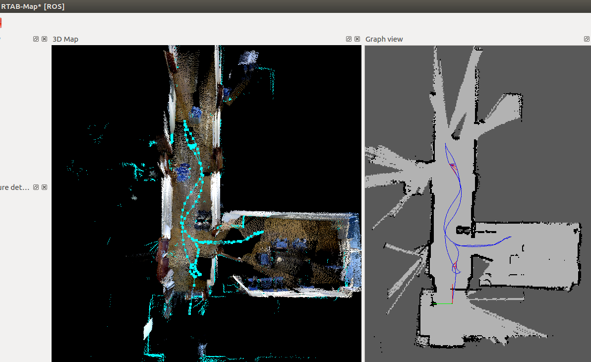 but there is still a TF error between base frame and the camera frame. The laser scans don't match exactly with the cloud created from the camera. Here some examples: 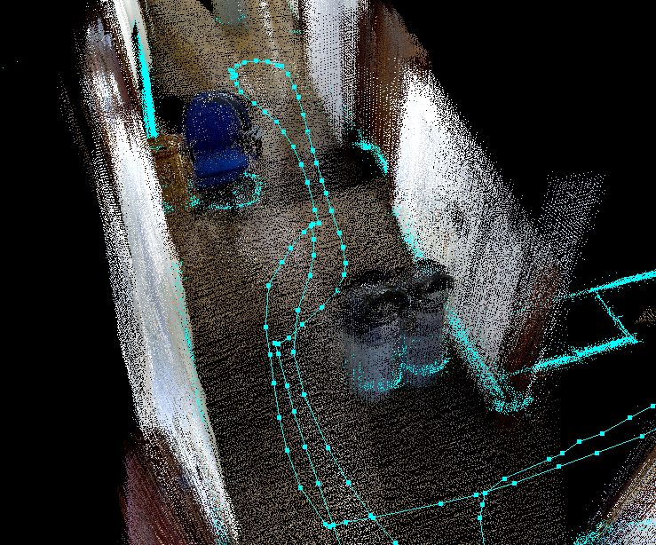 Look how the yellow dots from the scan don't match with the cloud from the camera. 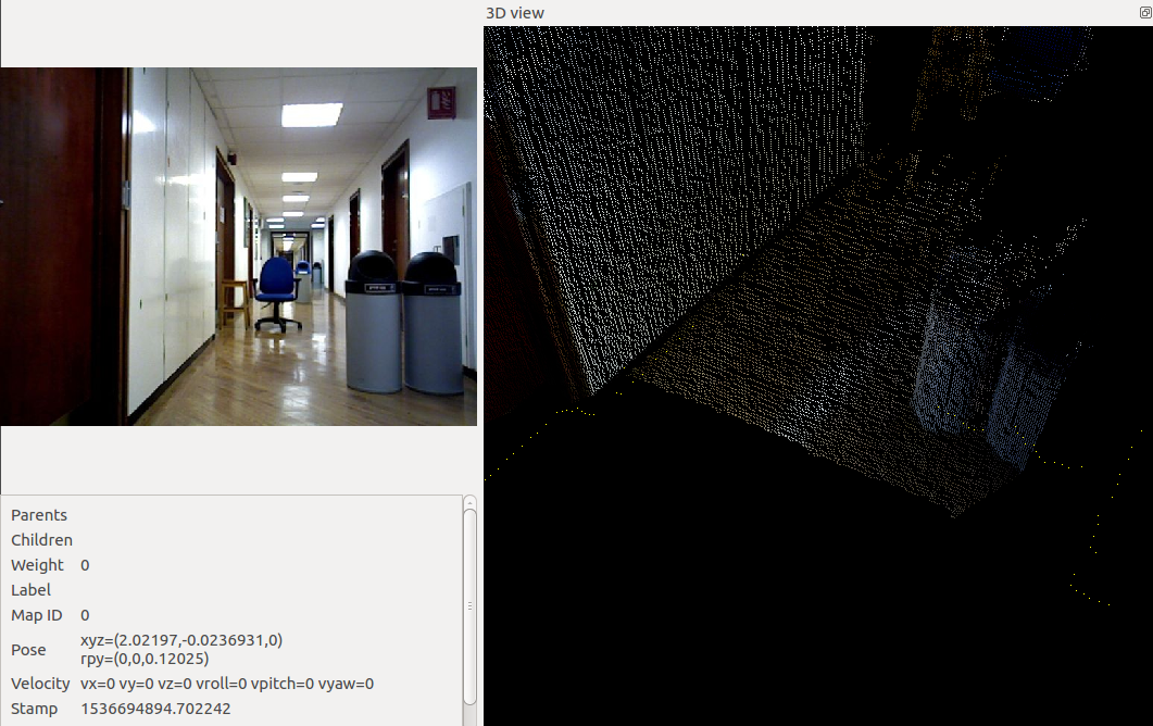 Another offset in rotation in the "12" bag: 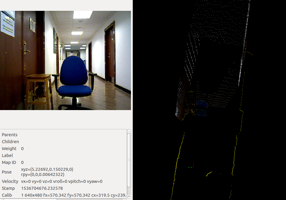 Following is another problem, this is only one scan. The bottom shows two layers of scans, how did you merge the scans from the 3 lidars? Maybe some TF tuning to get the scans overlaying each other. 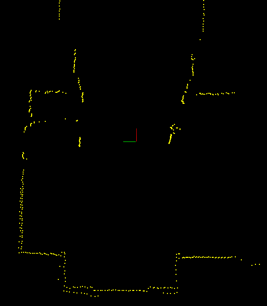 cheers, Mathieu |
Re: RTAB-Map and Unity integration
|
|
Hi,
Thanks for the script and the tip on the covariances. I tried to optimize this, but it seems like there is always some misalignment in one pose or another. For example, when adjusting the x position of the camera, so that the laser readings and the point cloud would be aligned, it seemed that it needed different values depending on whether the obstacle was close or far away. I don't know if this is a problem of the lasers (Hokuyo) or a camera (Asus) distortion, or how to fix it. I noticed this problem too (more or less same as above, there is always some misalignment no matter what values are used for tf) but wasn't aware that it could impact the mapping performance. We have 3 laser scanners and also use a custom node to merge the readings together. I was passing the merged reading to hector_mapping. I'll make a test of a run using only one of the lasers, see if it improves something. In the meantime, I noticed that when loop closure is detected, the 2d map generated by rtabmap gets realigned, but the point clouds seem to don't update as much, remaining misaligned sometimes. I'm wondering if is there some parameter that I should tweak to improve this, or do you think it's just the tf problem? Cheers, Vinicius |
|
Administrator
|
Hi,
You are using the Asus, it has quite distortions after 3/4 meters. Maybe just align well the camera so that camera cloud and scan match well under 4 meters. When rendering the clouds form the camera, set a maximum depth to to 3/4 meters (to show in 3D map only points from the camera matching well the scans). Depth distortion could be decreased using the CLAMS approach integrated in RTAB-Map: https://github.com/introlab/rtabmap/wiki/Depth-Calibration For the lidars, physically move the lidar that is offset from the others and watch RVIZ at the same time until they match together. Afterward, fine tune back TF to new real physical location. For "the point clouds seem to don't update", which topic are you referring? The generated cloud /rtabmap/cloud_map should be updated on loop closure. cheers, Mathieu |
Re: RTAB-Map and Unity integration
|
|
This post was updated on .
Hi,
Thanks for the tips. I've given an initial shot at the CLAMS calibration, following the link you sent, but no success so far (I'll try more tomorrow). But in the meantime, I wanted to check if it was possible to limit the points used by rtabmap to a "less-distorted" region, i.e. center of the image and close to the camera, and check if is there any improvement. I can't seem to find out the correct parameters to do that though. I've tried Grid/RangeMax, Grid/DepthRoiRatios, Kp/MaxDepth and Vis/MaxDepth, but I couldn't notice much change. Is there some other that I'm missing? For example, in your previous reply here, on the second figure, you mentioned how the scans become correctly aligned after the loop closure, but the point clouds remained misaligned. I was wondering if this is just because of the camera distortion/tf problem or is there some parameter that I could change to improve this. Cheers, Vinicius |
|
Administrator
|
Hi,
It is possible to filter a region in the depth image that we don't want to project to point cloud. The parameter is indeed Grid/DepthRoiRatios, not sure why it didn't work on your side. Here is a small example to keep only top left of the images: $ roslaunch rtabmap_ros args:="-d --Grid/DepthRoiRatios \"0 0.4 0 0.4\"" rtabmap.launch rviz:=true rtabmapviz:=false Showing MapCloud (without depth filtering): 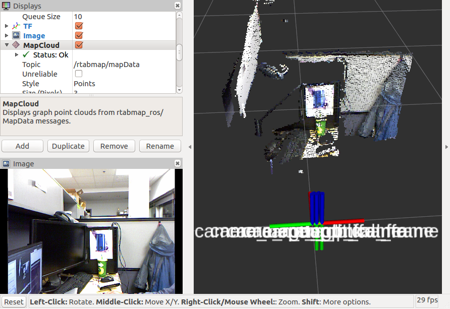 Showing rtabmap/cloud_map topic (with Grid/DepthRoiRatios): 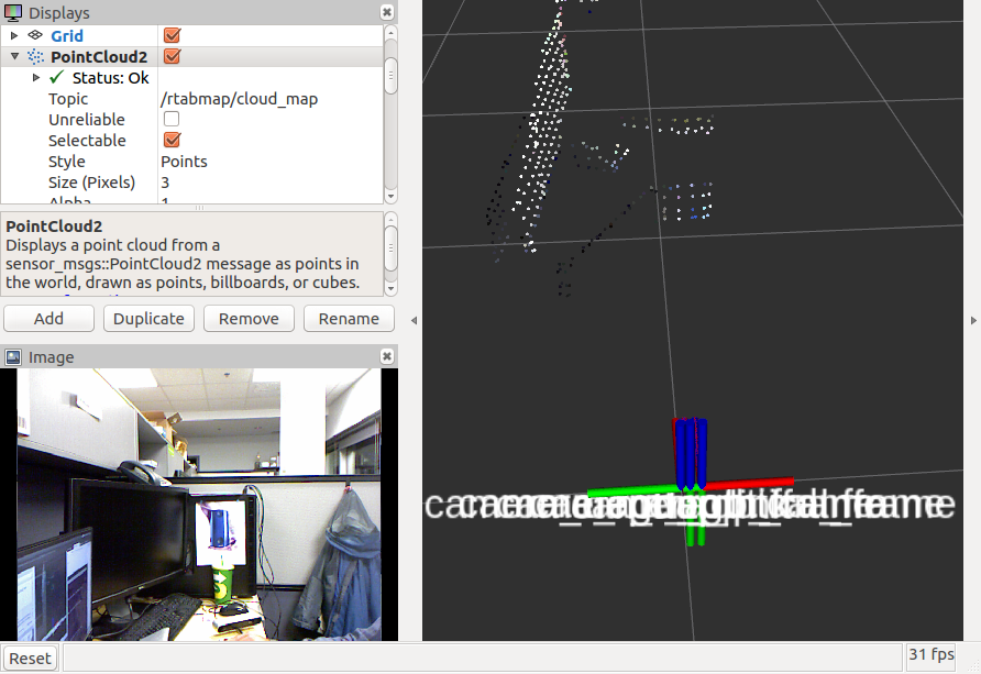 Note that the ratio should be under 0.5 to avoid errors, here is the order of the ratios: $ rtabmap --params | grep Grid/DepthRoiRatios Param: Grid/DepthRoiRatios = "0.0 0.0 0.0 0.0" [[Grid/FromDepth=true] Region of interest ratios [left, right, top, bottom].] In my reply, the scans and clouds are actually corrected on loop closures, but as the camera transform TF to scan is wrong, the clouds look not corrected but they are (rtabmap doesn't correct the wrong TF between lidar and camera). cheers, Mathieu |
Re: RTAB-Map and Unity integration
|
|
Hi Mathieu,
It was because when setting subscribe_scan to true rtabmap defaults Grid/FromDepth to false and then I couldn't actually observe the difference. But I think this is still not quite the effect I was looking for. Is there a way to filter the clouds before they are processed by rtabmap? I mean something similar to what we get when using the "regenerate clouds" option on the gui when exporting the 3d map, but live, so that noisy cloud points don't get registered on the wrong place. In any case, I'm still unable to get a good map of my environment. So I built this "minimal case" example to help me debug the problems I'm having. I was hoping you could also help me with it. First, I followed all the procedures for camera calibration recommended on rtabmap page, both regular for rgb and depth and also the CLAMS approach. After this, I ran rtabmap standalone (built from source) with the handheld camera inside my lab; screenshots of the results are below. It has some distortions, but the general shape of objects is preserved. 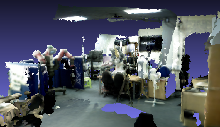 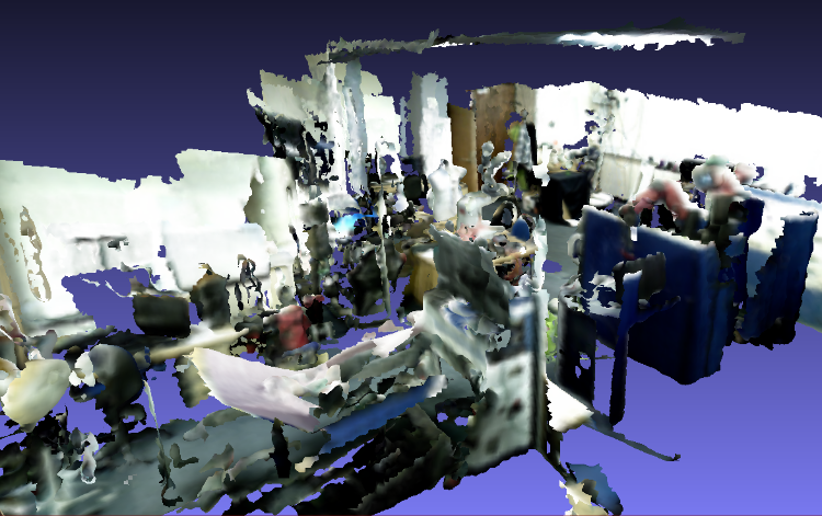 After that, I tried the same thing on the corridor outside of the lab, which I wanted to map: 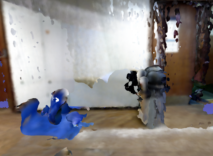 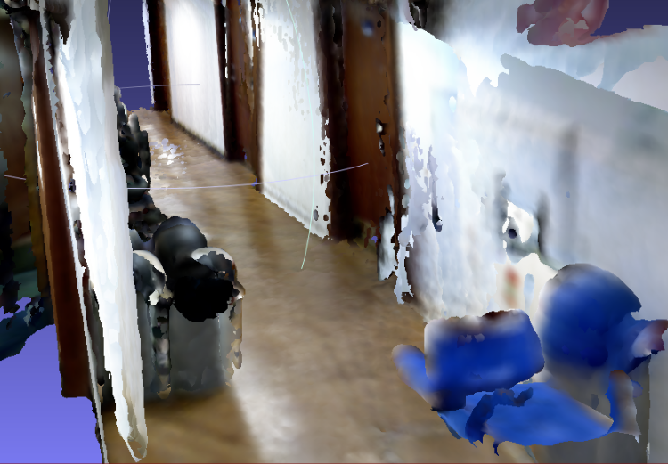 But this time I get the distorted objects. My only conclusion is that this environment is harder to map, due to fewer features on the images (and maybe small repetitive patterns on the floor?). So, my followup is to add the laser scanners to see if odometry can be improved. This time, to reduce TF alignment problems, I used only the best laser scanner in our robot, which is on its back. Using just this with hector_mapping gives me a pretty good 2D mapping and localization accuracy, as can be seen in the figure below. 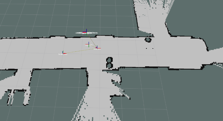 So I thought that this would surely help with improving the 3D mapping quality. I put up the Asus camera facing the same direction as the laser and got the best possible tf alignment, focusing especially on closer ranges, as you had recommended. However, to my surprise, the laser+hector does not help much, and might even decrease performance a little, as can be seen below: 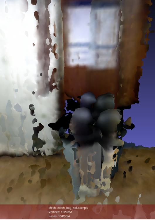 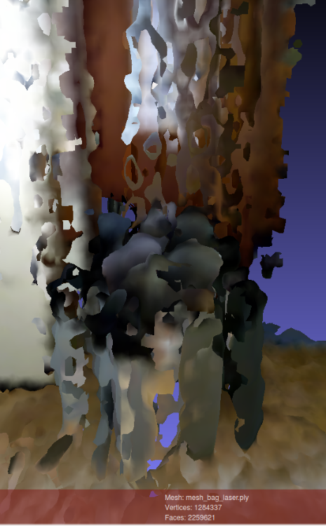 Both meshes above were built with the same bag, which I copied (compressed) to this link. For the laser-based odometry, I used a custom launch file (also added to the link), adapted from demo_hector_mapping.launch of the tutorials. I just ran this file with bag:=true argument. For the camera only setup, I simply filtered tf messages from the bag and ran: roslaunch rtabmap_ros rtabmap.launch rtabmap_args:="--delete_db_on_start" rgb_topic:=/camera/data_throttled_image depth_topic:=/camera/data_throttled_image_depth camera_info_topic:=/camera/data_throttled_camera_info use_sim_time:=true rviz:=true I also copied to the link the rtabmap databases generated after the run and the exported mesh files. Finally, I noticed that the 2 above setups seem to fail for different reasons. With the camera only, the problem seems to be a poor odometry on the x-axis of the path, as objects surfaces appear relatively smooth, but their fronts and backs are not correctly aligned, even after loop closure is detected. With the laser setup, on the other hand, there is this weird behaviour that can be observed around 33 seconds of the bag. Before it, the trash can is being mapped fine, but after that new points start to be added with a depth off-set. I would think this is a camera distortion problem, but when using the camera-only setup, the problem doesn't occur. So, now I don't really know where to go with my "minimal case debug" attempt, or how to improve the quality of the 3D maps. Any insights? Sorry for the long post, but I wanted to describe all the steps I've taken, to see if anything can help. Cheers, Vinicius |
|
Administrator
|
Hi Vinicius,
Yes, we can use the scan_cloud input (with subscribe_scan_cloud:=true) to feed any point clouds to rtabmap, but we cannot subscribe to a laser scan at the same time. However, to keep the laser scan input, with Grid/FromDepth to true, there are already many filtering approaches available in rtabmap: $ rtabmap --params | grep Grid/ Param: Grid/3D = "true" [A 3D occupancy grid is required if you want an OctoMap (3D ray tracing). Set to false if you want only a 2D map, the cloud will be projected on xy plane. A 2D map can be still generated if checked, but it requires more memory and time to generate it. Ignored if laser scan is 2D and "Grid/FromDepth" is false.] Param: Grid/CellSize = "0.05" [Resolution of the occupancy grid.] Param: Grid/ClusterRadius = "0.1" [[Grid/NormalsSegmentation=true] Cluster maximum radius.] Param: Grid/DepthDecimation = "4" [[Grid/DepthDecimation=true] Decimation of the depth image before creating cloud. Negative decimation is done from RGB size instead of depth size (if depth is smaller than RGB, it may be interpolated depending of the decimation value).] Param: Grid/DepthRoiRatios = "0.0 0.0 0.0 0.0" [[Grid/FromDepth=true] Region of interest ratios [left, right, top, bottom].] Param: Grid/FootprintHeight = "0.0" [Footprint height used to filter points over the footprint of the robot. Footprint length and width should be set.] Param: Grid/FootprintLength = "0.0" [Footprint length used to filter points over the footprint of the robot.] Param: Grid/FootprintWidth = "0.0" [Footprint width used to filter points over the footprint of the robot. Footprint length should be set.] Param: Grid/FromDepth = "true" [Create occupancy grid from depth image(s), otherwise it is created from laser scan.] Param: Grid/MaxGroundHeight = "0.0" [Maximum ground height (0=disabled). Should be set if "Grid/NormalsSegmentation" is false.] Param: Grid/MaxObstacleHeight = "0.0" [Maximum obstacles height (0=disabled).] Param: Grid/MinClusterSize = "10" [[Grid/NormalsSegmentation=true] Minimum cluster size to project the points.] Param: Grid/MinGroundHeight = "0.0" [Minimum ground height (0=disabled).] Param: Grid/NoiseFilteringMinNeighbors = "5" [Noise filtering minimum neighbors.] Param: Grid/NoiseFilteringRadius = "0.0" [Noise filtering radius (0=disabled). Done after segmentation.] Param: Grid/PreVoxelFiltering = "true" [Input cloud is downsampled by voxel filter (voxel size is "Grid/CellSize") before doing segmentation of obstacles and ground.] Param: Grid/RangeMax = "5.0" [Maximum range from sensor. 0=inf.] Param: Grid/RangeMin = "0.0" [Minimum range from sensor.]What kind of filtering would you want to use? I can refer you to the correct parameters above. Here are the main PCL filters implemented by some of the above parameters: VoxelGrid, Passthrough, Cluster extraction, Crop box and RadiusOutliers removal. With visual odometry, the map looks good until the robot rotated in front of a wall/door without discriminative visual features. Here are two examples where the odometry drifted a lot more (look at the top left image, which is the image used for odometry): 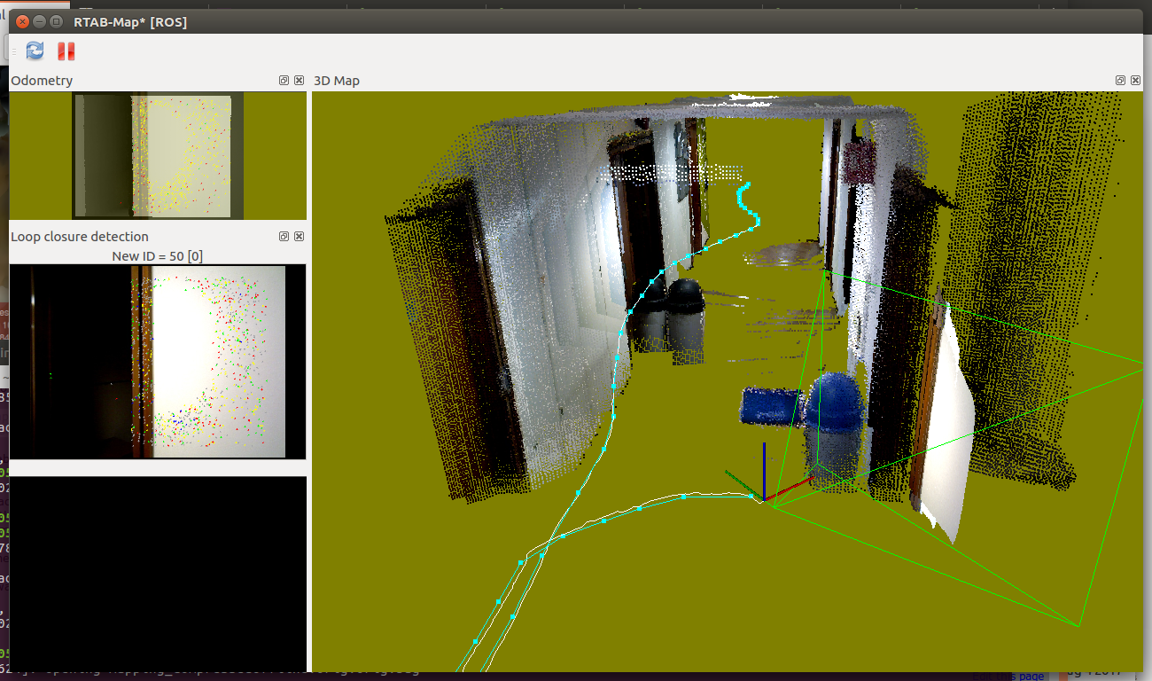 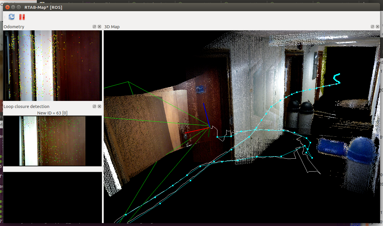 We can see in rtabmapviz the white line (i.e., odometry trajectory) having small noisy jumps. Afterwards, loop closures correct roughly the biggest errors, but indeed not all errors. The best would be to rotate in front of a billboard instead of a white wall (to avoid yellow/red odometry background in rtabmapviz). If the robot should navigate autonomously (the roobt doesn't know when the area is good or not for visual odometry), using the lidar is a lot more robust. For the lidar experiment, the 2D map is accurate but not the 3D map. The camera TF seems slightly off the lidar (look how the scan, yellow dots, doesn't match the corresponding cloud from the camera): 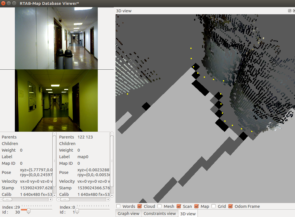 I also noticed that it seems to have also a scale problem with the camera. The scale of the depth image may be wrong or a wrong focal distance is set in the calibration. Look at the following images of the same node in the map (see 3D View in rtabmap-databaseViewer), notice how on left the cloud is inside the laser scan and on right, the cloud is also inside the laser scan: 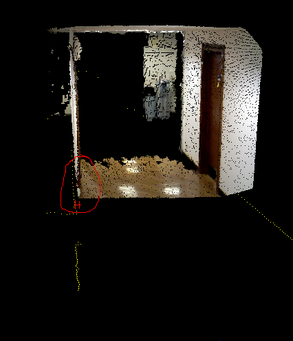 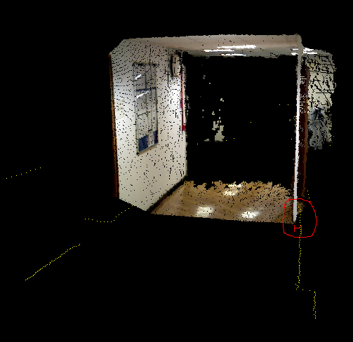 Ideally, try to fix the scale (camera calibration or depth image scaling) before readjusting the TF to match the laser scan. cheers, Mathieu |
Re: RTAB-Map and Unity integration
|
|
Hi Mathieu,
Thanks for the analysis and reply. The filtering that I was looking for is to try to correct this problem that I described happening around 33s of the bag. I noticed that until then, the points on the map (especially noticeable on the trash bin) were being added to the correct location but afterwards there is an offset. Since the robot was further away from the object by this time, I'm wondering if this is a camera depth distortion problem (despite calibration). If that is the case, I would like to somehow discard data for points that are at a longer distance. Like I said, I played with some parameters but couldn't observe this effect. Regarding calibration and tf adjustments, I've put quite some effort into this, but everything seems to be very sensitive. The tf transforms have to be fixed, but whatever I set seems to only be valid for a short range of distances/angles. Is this a camera problem? Any other advices to cope with this? Also, from your experience, does the Kinect camera significantly improve results in relation to the Asus Xtion? Or is it more or less the same? Cheers, Vinicius |
|
Administrator
|
Hi,
I don't see a problem at 33 sec in the bag, here is the screenshot of the map so far: 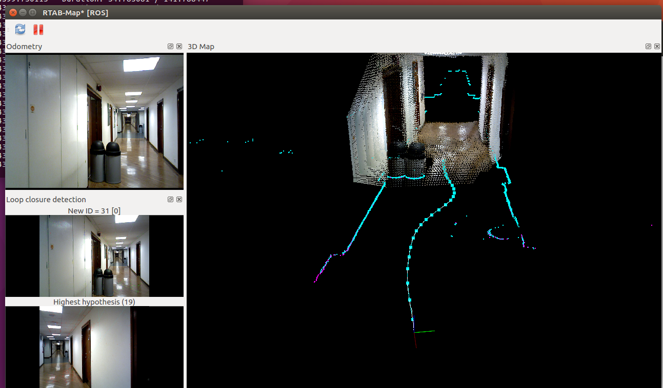 Note that because of the camera scale and TF problem, the clouds are already not aligned with the scans, here a close up of the image above around the trash cans: 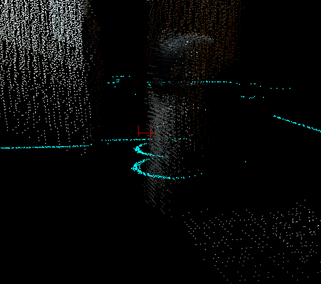 The clouds look more farther than the scans. Imagine now that you are coming back, it will make sure that the trash can's clouds will overlap even if the scans are perfectly aligned, here the example (at ~110 sec, in yellow where the trash can's cloud should be in reality based on the scans), 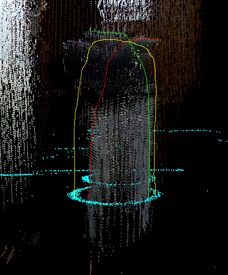 It can be quite hard indeed to get all sensors correctly aligned and in the same scale. The question is "Is it really a problem that the clouds are not aligned perfectly with the scans?" For navigation, I don't think so if the error is below 2.5 cm. For accurate 3D reconstruction, it is indeed a problem, so careful calibration and sensor alignment are required. From the Xtion I have, it has more distortion (over 3 meters) than my kinect 360, not sure if this applies to all Xtion. The Kinect for Xbox One is a TOF sensor, maybe easier to get the scale right. I didn't do myself experiments to evaluate the scale precision of the different sensors, maybe some papers did it. I know however that in the TUM RGBD-D dataset, the scale of the depth image or the calibration can be a little off from the ground truth on some sequences. More related to your experiment with lidar, see the second bullet point of Section 4.4 in this paper "RTAB-Map as an Open-Source Lidar and Visual SLAM Library for Large-Scale and Long-Term Online Operation" about matching the lidar and the stereo/rgb-d camera of the MIT Stata Center dataset: Note however that we only tested localization performance, not the reconstruction quality (e.g., 3D map created from lidar odometry vs 3D map created from visual odometry vs 3D map created from wheel odometry). cheers, Mathieu |
«
Return to Official RTAB-Map Forum
|
1 view|%1 views
| Free forum by Nabble | Edit this page |