Re: RTAB-Map and Unity integration
Posted by matlabbe on
URL: http://official-rtab-map-forum.206.s1.nabble.com/RTAB-Map-and-Unity-integration-tp4925p5109.html
Hi Vinicius,
With visual odometry, the map looks good until the robot rotated in front of a wall/door without discriminative visual features. Here are two examples where the odometry drifted a lot more (look at the top left image, which is the image used for odometry):
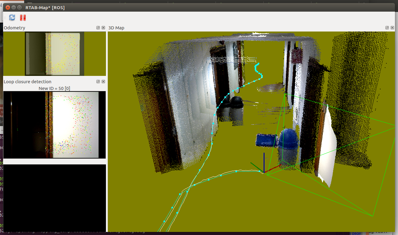
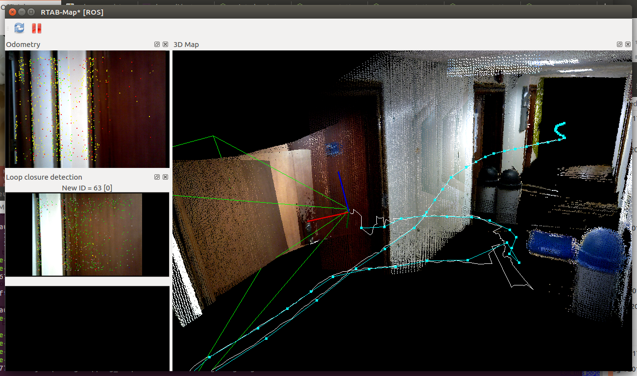
We can see in rtabmapviz the white line (i.e., odometry trajectory) having small noisy jumps. Afterwards, loop closures correct roughly the biggest errors, but indeed not all errors. The best would be to rotate in front of a billboard instead of a white wall (to avoid yellow/red odometry background in rtabmapviz). If the robot should navigate autonomously (the roobt doesn't know when the area is good or not for visual odometry), using the lidar is a lot more robust.
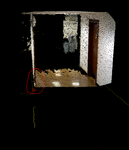
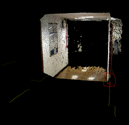
For the lidar experiment, the 2D map is accurate but not the 3D map. The camera TF seems slightly off the lidar (look how the scan, yellow dots, doesn't match the corresponding cloud from the camera):
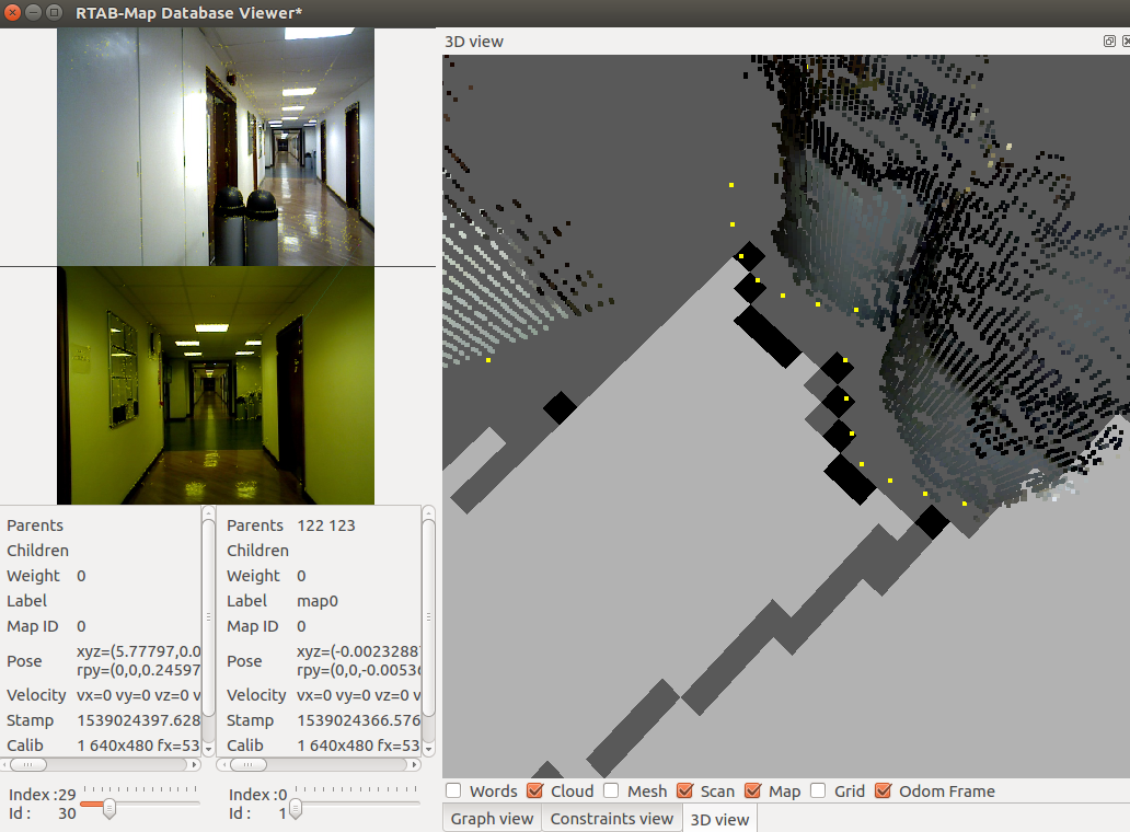
I also noticed that it seems to have also a scale problem with the camera. The scale of the depth image may be wrong or a wrong focal distance is set in the calibration. Look at the following images of the same node in the map (see 3D View in rtabmap-databaseViewer), notice how on left the cloud is inside the laser scan and on right, the cloud is also inside the laser scan:
Ideally, try to fix the scale (camera calibration or depth image scaling) before readjusting the TF to match the laser scan.
cheers,
Mathieu
URL: http://official-rtab-map-forum.206.s1.nabble.com/RTAB-Map-and-Unity-integration-tp4925p5109.html
Hi Vinicius,
Yes, we can use the scan_cloud input (with subscribe_scan_cloud:=true) to feed any point clouds to rtabmap, but we cannot subscribe to a laser scan at the same time. However, to keep the laser scan input, with Grid/FromDepth to true, there are already many filtering approaches available in rtabmap:
$ rtabmap --params | grep Grid/
Param: Grid/3D = "true"                                    [A 3D occupancy grid is required if you want an OctoMap (3D ray tracing). Set to false if you want only a 2D map, the cloud will be projected on xy plane. A 2D map can be still generated if checked, but it requires more memory and time to generate it. Ignored if laser scan is 2D and "Grid/FromDepth" is false.]
Param: Grid/CellSize = "0.05"                              [Resolution of the occupancy grid.]
Param: Grid/ClusterRadius = "0.1"                          [[Grid/NormalsSegmentation=true] Cluster maximum radius.]
Param: Grid/DepthDecimation = "4"                          [[Grid/DepthDecimation=true] Decimation of the depth image before creating cloud. Negative decimation is done from RGB size instead of depth size (if depth is smaller than RGB, it may be interpolated depending of the decimation value).]
Param: Grid/DepthRoiRatios = "0.0 0.0 0.0 0.0"             [[Grid/FromDepth=true] Region of interest ratios [left, right, top, bottom].]
Param: Grid/FootprintHeight = "0.0"                        [Footprint height used to filter points over the footprint of the robot. Footprint length and width should be set.]
Param: Grid/FootprintLength = "0.0"                        [Footprint length used to filter points over the footprint of the robot.]
Param: Grid/FootprintWidth = "0.0"                         [Footprint width used to filter points over the footprint of the robot. Footprint length should be set.]
Param: Grid/FromDepth = "true"                             [Create occupancy grid from depth image(s), otherwise it is created from laser scan.]
Param: Grid/MaxGroundHeight = "0.0"                        [Maximum ground height (0=disabled). Should be set if "Grid/NormalsSegmentation" is false.]
Param: Grid/MaxObstacleHeight = "0.0"                      [Maximum obstacles height (0=disabled).]
Param: Grid/MinClusterSize = "10"                          [[Grid/NormalsSegmentation=true] Minimum cluster size to project the points.]
Param: Grid/MinGroundHeight = "0.0"                        [Minimum ground height (0=disabled).]
Param: Grid/NoiseFilteringMinNeighbors = "5"               [Noise filtering minimum neighbors.]
Param: Grid/NoiseFilteringRadius = "0.0"                   [Noise filtering radius (0=disabled). Done after segmentation.]
Param: Grid/PreVoxelFiltering = "true"                     [Input cloud is downsampled by voxel filter (voxel size is "Grid/CellSize") before doing segmentation of obstacles and ground.]
Param: Grid/RangeMax = "5.0"                               [Maximum range from sensor. 0=inf.]
Param: Grid/RangeMin = "0.0"                               [Minimum range from sensor.]
What kind of filtering would you want to use? I can refer you to the correct parameters above. Here are the main PCL filters implemented by some of the above parameters: VoxelGrid, Passthrough, Cluster extraction, Crop box and RadiusOutliers removal.
With visual odometry, the map looks good until the robot rotated in front of a wall/door without discriminative visual features. Here are two examples where the odometry drifted a lot more (look at the top left image, which is the image used for odometry):
We can see in rtabmapviz the white line (i.e., odometry trajectory) having small noisy jumps. Afterwards, loop closures correct roughly the biggest errors, but indeed not all errors. The best would be to rotate in front of a billboard instead of a white wall (to avoid yellow/red odometry background in rtabmapviz). If the robot should navigate autonomously (the roobt doesn't know when the area is good or not for visual odometry), using the lidar is a lot more robust.
For the lidar experiment, the 2D map is accurate but not the 3D map. The camera TF seems slightly off the lidar (look how the scan, yellow dots, doesn't match the corresponding cloud from the camera):
I also noticed that it seems to have also a scale problem with the camera. The scale of the depth image may be wrong or a wrong focal distance is set in the calibration. Look at the following images of the same node in the map (see 3D View in rtabmap-databaseViewer), notice how on left the cloud is inside the laser scan and on right, the cloud is also inside the laser scan:
Ideally, try to fix the scale (camera calibration or depth image scaling) before readjusting the TF to match the laser scan.
cheers,
Mathieu
| Free forum by Nabble | Edit this page |