Rtabmap mapping with two cameras
1234


1234
Re: Rtabmap mapping with two cameras
|
Hello,
so then cameras timestamps are more or less synchronized as you can see: 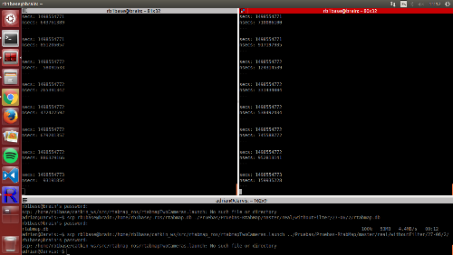 I have recorded a new database with the odom_sensor_sync and the other params, as well as the static transforms, although I am not sure about the frames. I attatch the launch rtabmap.launch and the database. Can this be improved or is it a matter of limitation of the cameras movement? Regards |
Re: Rtabmap mapping with two cameras
|
Administrator
|
Hi,
The map quality depends on many factors (odometry accuracy, scan matching accuracy, sensor position/orientation on the robot with corresponding accurate TF, time synchronization between odom/lidar/camera,...), but here I think most of them have been improved. Looking at the database, unless there are distorsions in the camera, it seems that TF of the cameras could have more improvements. The transform between odometry frame and Lidar frame could be also refined. Here is an example: 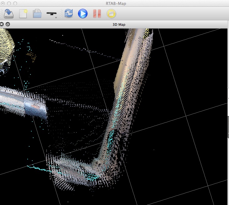 When hitting "o" key on the keyboard while focusing the 3d Map view, we enter Ortho mode. The walls in this mode, when looking from top, should be a line. They are not, the TF of the cameras may not correctly correspond with the real world. The walls and scans should also match one over the other. Note that more and more sensors are integrated, extrinsics calibration should be even more precise between all sensors (as well as good time synchronization). Depending on what you need to do, the maps that your robot is currently created may be usable even if they are not perfect. cheers, Mathieu |
Re: Rtabmap mapping with two cameras
|
Hello, so i have been checking the TFs and eveything looks enough synchronized, and I have fixed that stuff of the laser scans.
Also, We have been testing with the robot with different configurations, no laser or with laser, visual odometry vs robot odometry, one or two cameras, different movements, etc. You can see how the maps were created in the following youtube list I have created. I update here the database and the launch file of the most recent video. As you can see the loop closures / matches are not well done, since the transformation from one hypothesis to the current image has some trouble, and that is the reason why I was saying in previous posts that things appear "twice". Even limiting the minimum number of features to accept a new hypothesis, the transform is still done bad, as you can see in this pictures:  Feature matching is more or less done (maybe not enough matches for the number of features detected, but I guess this is due to limitations of ORB algorithm), but when it comes to merging them it fails:  Is there any parameter that I might change to try to get something better as our goal was to have quality good enough so that we can later do 3D object recognition with some special stuff of the map. Thanks and cheers |
|
Administrator
|
Do you have the database of your "most recent video"? Normally visual loop closure should be better than that. What could happen is on the ICP refining step, which can add errors. Looking at that particular video, if ICP is enabled, ICP may require some tuning because you should not have so much drift with a lidar hitting most walls around the robot. If lidar Tf is slightly off the camera TF, ICP refining can "destroy" the actual good visual loop closure. With the database I will be able to tune ICP parameters to see if the drift can be decreased.
cheers |
Re: Rtabmap mapping with two cameras
|
Administrator
|
Hi,
I've been playing with rtabmap5.db, and here some thoughts: 1- In database viewer, some neighbor links have very high variance (>=9999), which is bad if the data was taken continuously in the same session. 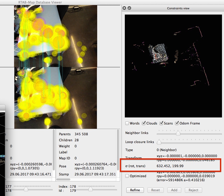 2- For the best I can do by adding refining/adding manually loop closures, The trajectory, from the camera point of view, is not a pure 360 rotation. This kind of effect is caused by camera TF offset error against base_link. There is then a battle between odometry/laser telling that it is a pure rotation, and camera telling not. As odometry/laser angular variance is smaller, it wins. Trajectory (visual optimized): 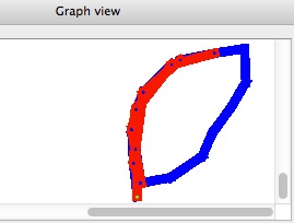 Double effect: 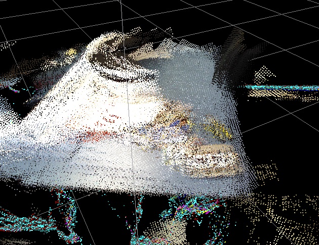 With visual optimizations. The "double desk" error on the left is caused by odometry drift + wrong base_link->camera_link transform, as no visual optimization could be done there. In contrast on the right desk, all neighbor links could be refined by visual, so the result is good (no more double effect). 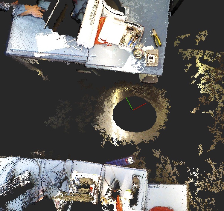 3- If I activate ICP neighbor link refining and tune ICP parameters (voxel 1 cm and correspondences 2 cm), here is a comparison before the first loop between odometry and just ICP corrections: Pure robot odom: 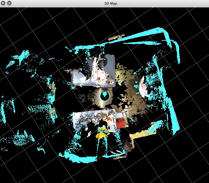 ICP refining (RGBD/NeighborLinkRefining=true, Icp/MaxCorrespondenceDistance=0.02, Icp/VoxelSize=0.01): 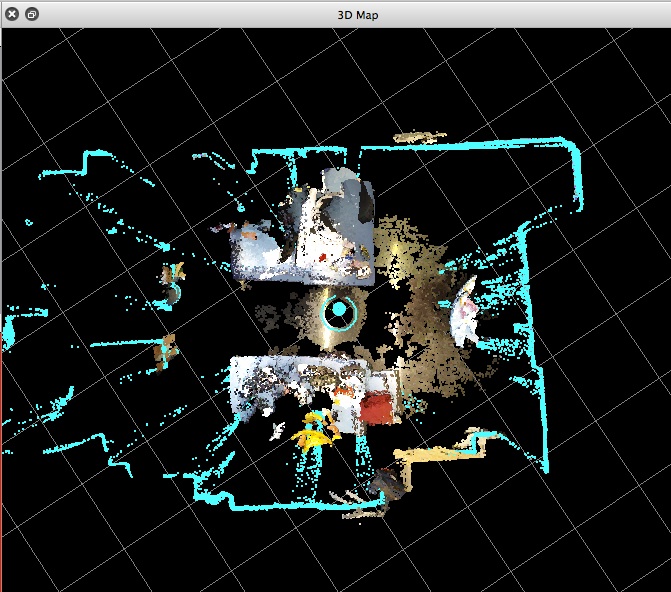 You can also filter laser scan points in range under 50 cm to avoid points "on the robot" that could have an effect on registration: 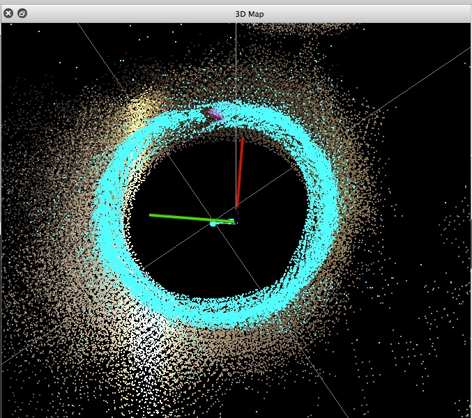 Final Map after 3 loops and with loop closure detections: 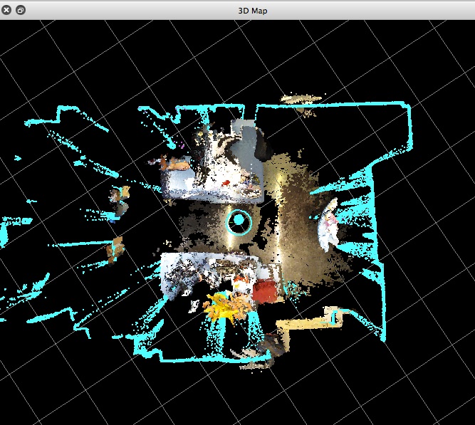 The laser scans are almost perfectly aligned, so the map is good. For the corresponding point clouds, there is still a double effect. Here it is really the transform between base_link and camera_link that is wrong, because the map (from the laser scan point of view) is almost perfect. 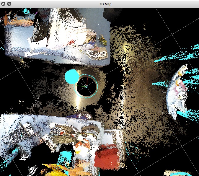 My final thoughts: use ICP parameters as I set above, then adjust the TF between base_link and camera_link. You should have something similar than the results without double effect above if the camera is correctly aligned with the laser/base_link. cheers, Mathieu |
Re: Rtabmap mapping with two cameras
|
This post was updated on .
Hello, thanks for the reply.
I had a problem with the cameras position with respect to base_link. It was written that the cameras were on the center on the robot, but they are actually 20cm ahead. This is probably what was causing the base_link camera_link transform error and why when I rotated i had this double effect and not when I was moving only forward. Anyway, I would like to know how did you know this was the problem and how did you extract that trajectory graph. This way I can confirm if the error was only this position offset. I am now clearly having better results but when I look into the same table, for example, from different angles (lets say one look placed in the front of the table and another look placed in the right of the table, looking at the same elements) I have still this double effect on the limits of the table and some items. Is this due to limitations on the ICP algorithm (seeing the same item from different angles)? Another thing is, what do you mean with "bad" about the variance of the neighbours? Is it because I have run multiple times over the same parts of the map (data was taken continuously yes)? Is it possible to have some graphs with information like: loop closures against odometry positions, or number of loop closures against number of neighbours or rejected loop closures...? Additionally, when I set "approx_sync" to false in the "rgbd_sync" nodes, the mapping is not working (always yellow warns that there is no data received) and I have checked the /header/stamp in each of the cameras and each /rgb and /depth and they are the same. However, when I use "rostopic hz" into two of them it takes a while to synchronize both outputs. Appart from this, I would like to clarify the mapping process done internally: 1- Take rgb and depth image from cameras and sync them into one rgbd image to be the essential data for mapping. 2- Synchronize rgbd with odom (or visual odom) and laser. 3- every time there is a change in one of the elements above, a new node in the graph (what is this graph??) is added with the new data. 4- From this new node the features are computed and checked if the node is a neighbour of previous nodes or it is a loop closure (robot placed in the same position as some node before). 5- graph is updated with new loop closure or new neighbour? Anything missing or relevant appart from this? I will upload other database with better results later on. Cheers and thanks. |
|
Administrator
|
From the last results I've shown, the problem is not ICP, it is pretty accurate. The double effect is mainly caused by wrong TF between base_link and camera. Also make sure base_link to lidar is accurate too (so that indirectly lidar to camera is accurate).
I used rtabmap-databaseViewer, opened Graph View tab to see the trajectory. You may need to zoom and decrease line/node width (right-click options) to see it clearly like in my screenshot. I set Reg/Strategy to 0, Vis/MinInliers to 10, then hit Edit->Refine all neighbor links and all loop closure links. That way we can see the trajectory that could be done if ICP was not used, so in camera reference frame. That gave the point cloud above without double effect. I think the scans were not well registered in this mode. Conclusion: If the 2d map is good with ICP, and the 3D map is good with visual-only refining, that means that the transform between lidar and camera is wrong (one of base_link->camera_link or base_link->scan or both). For the odometry, how variance of odometry is computed? is it fixed? $ rostopic echo /odom For synchronization, camera_info topic should have also the same timestamp. Topics should have the same framerate. For the steps, a new node is created if the robot has moved at least 10 cm or rotated 10 radians (default). Parameters are called RGBD/AngularUpdate and RGBD/LinearUpdate. The graph is the structure of the map, see paper "Online Global Loop Closure Detection for Large-Scale Multi-Session Graph-Based SLAM". A new node is always added to map, even if there is a loop closure or not. cheers, Mathieu |
Re: Rtabmap mapping with two cameras
|
Thanks for the reply, I hope I am now able to detect those problems by my self.
One thing I do not complete understand is the differentiation of "loop closure detection vs accepting loop closures". From the paper, I understood that the loop closure first has to be detected by the bag of words approach, computing a likelihood of how much similar are the visual words of the current node with the visual words of the loop closure node. Then, if the loop closure hypothesis is accepted, which means a loop closure is detected, then a RANSAC algorithm is used to compute the number of inliers between the visual words of the nodes. If this number of inliers is higher than a threshold then the loop closure is accepted; but, if the number of inliers is not that high, the loop closure is not accepted and thus the link is not added. So, this means that even if a loop closure is detected there is another step next in which we can decide whether to accept it or not. But then the parameters of rtabmap for //Verify Hypothesis talk about RANSAC, so these parameters are to ACCEPT the loop closure and not to DETECT (accept the detection) of the loop closure. There are also others in // Hypotheses selection which are used for this last detection. Am I right? Or is it that a hypothesis is detected (selected) with the bag of words approach, then the ransac is used to get the match of this hypothesis with the current image, if the constraint is not met, then ANOTHER HYPOTHESIS IS FOUND and again there is the acceptance step. Regards |
Re: Rtabmap mapping with two cameras
|
Also, what step (loop clpsure aceptance vs detection of loop closure) do these parameters refer to?
RTABMAP_PARAM(RGBD, ProximityByTime, bool, false, "Detection over all locations in STM."); RTABMAP_PARAM(RGBD, ProximityBySpace, bool, true, "Detection over locations (in Working Memory) near in space."); RTABMAP_PARAM(RGBD, ProximityMaxGraphDepth, int, 50, "Maximum depth from the current/last loop closure location and the local loop closure hypotheses. Set 0 to ignore."); RTABMAP_PARAM(RGBD, ProximityMaxPaths, int, 3, "Maximum paths compared (from the most recent) for proximity detection by space. 0 means no limit."); RTABMAP_PARAM(RGBD, ProximityPathFilteringRadius, float, 0.5, "Path filtering radius to reduce the number of nodes to compare in a path. A path should also be inside that radius to be considered for proximity detection."); RTABMAP_PARAM(RGBD, ProximityPathMaxNeighbors, int, 0, "Maximum neighbor nodes compared on each path. Set to 0 to disable merging the laser scans."); RTABMAP_PARAM(RGBD, ProximityPathRawPosesUsed, bool, true, "When comparing to a local path, merge the scan using the odometry poses (with neighbor link optimizations) instead of the ones in the optimized local graph."); RTABMAP_PARAM(RGBD, ProximityAngle, float, 45, "Maximum angle (degrees) for visual proximity detection."); |
|
Administrator
|
This post was updated on .
Hi,
Your analysis is correct. Here are some precisions, there a couple of ways to detect loop closures. 1- BOW [global] loop closure detection: When an loop closure hypothesis is over Rtabmap/LoopThr, a loop closure is detected. Depending if RTAB-Map is in RGBD-SLAM mode or just loop closure detection mode, the loop closure is verified in two ways. * In RGBD-SLAM mode (RGBD/Enabled=true), the loop closure will be accepted if there are at least "Vis/MinInliers" RANSAC inliers when computing the visual transformation. * In loop closure detection-only (RGBD/Enabled=false), as we don't have depth image, we can use "Rtabmap/VhStrategy=1" to verify with a fundamental matrix (I changed parameter name in this commit from "Rtabmap/VhStrategy" to "VhEp/Enabled" as there was only one strategy) with minimum "VhEp/MatchCountMin" RANSAC inliers. This could be also used in RGBD-SLAM mode but as the transformation estimation does already RANSAC, no need to do this twice. 2- Proximity [local] loop closure detection (only used in RGBD-SLAM mode): in a radius "RGBD/LocalRadius" around the current position, select the closest node to compute a transformation. Here "Vis/MinInliers" is also used to accept it or not. In both cases, if the verification fails, we don't look against other nearby nodes. We must wait until next map update to find a loop closure. If the verification succeeded, there is one last step that could reject the loop closure (in RGBD-SLAM mode). Parameter "RGBD/OptimizeMaxError" can be used to reject the loop closure if after optimizing the map with this new constraint, a lot of error appears in another link already in the graph. In general, "Vis/MinInliers=20" and "RGBD/OptimizeMaxError=0.1 or 0.05" can reject a large number of wrong loop closure hypotheses. cheers, Mathieu |
«
Return to Official RTAB-Map Forum
|
1 view|%1 views
| Free forum by Nabble | Edit this page |


